EasyManua.ls Logo

Philips Saeco New Royal User Manual

Philips Saeco New Royal
54 pages
To Next Page IconTo Next Page
Page #1 background imageLoading...
Page #1 background image
Service Manual
Revision 01 November 2015
Service
Coee Machine
HD 8930
New Royal
Table of contents Page
1. Introduction
1.1. Documentation required 1
1.2. Tools and equipment required 1
1.3. Material 1
1.4. Safety warnings 1
1.5
Service Policy
2
1.6. External machine parts 3
1.6. Internal machine parts 4
2. Technical specications
2.1. Technical specications 1
2.2. Machine parameters and performance 2
2.3. Specication for the measurement of the coee prod-
ucts temperature
4
2.3.1 Specication for the measurement of the Milk products
temperature
5
3. User instructions
3.1. Customer and programming menu 1
3.2. Machine indications 3
3.3. Operation, cleaning and maintenance 4
4. Operating logic
4.1. Water circuit 1
4.2. Frother unit valve assembly 2
4.3. Cappuccino maker assembly 2
4.4. Relief valve 3
4.5. Coee cycle 4
4.6. Single microswitch 5
4.7 Temperature sensor 5
Table of contents Page
4.8. Water level detection (water tank) 6
4.9. Descaling request 6
4.10. Water lter 7
5. Troubleshooting
5.1. Test mode 1
5.2. Diagnostics mode 5
5.3 Error messages 7
6.
Servicing and maintenance
6.1.
Repair Flow
1
7. Disassembly
7.1. Outer elements 1
7.2. Coee grinder 1
7.3. Grinder blades 2
7.4. Coee grinder motor 3
7.5. Doser hatch, coil and microswitch 3
7.6. Doser hopper 3
7.7. Coee boiler and steam boiler 4
7.8. Boiler pin 4
7.9. Coee pump and steam pump 4
7.10. Flow meter 5
7.11. Gear motor 5
7.12. Relief valve 6
7.13. Solenoid valve assembly 6
7.14. Steam pipe assembly 7
7.15. Dispenser assembly 7
7.16. Power board 7
All parts of this document are the property of Saeco International Group.
All rights reserved. This document and all the information herein is provided without liability deriving from any errors or omissions. Furthermore, no part may be reproduced,
used or collected, except where express authorization has been provided in writing or through a contractual agreement.
Published by Saeco International Group
Subject to modication EN 4219 400 013
2011-July-08
Question and Answer IconNeed help?

Do you have a question about the Philips Saeco New Royal and is the answer not in the manual?

Philips Saeco New Royal Specifications

General IconGeneral
Pump Pressure15 bar
Adjustable Coffee VolumeYes
Removable Brewing UnitYes
Hot Water DispenserYes
Adjustable Coffee QuantityYes
MaterialPlastic and metal
DisplayYes

Summary

Chapter 1: Introduction

1.1. Documentation Required

Lists necessary documentation for repair procedures.

1.2. Tools and Equipment Required

Details the tools and equipment needed for repairs.

1.3. Material

Lists required materials for maintenance.

1.4. Safety Warnings

Important safety precautions to observe during maintenance.

1.5. Service Policy

Outlines the service policy for repairs and component usage.

1.6. External Machine Parts

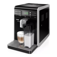
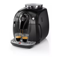
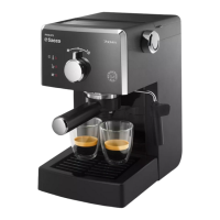
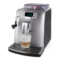
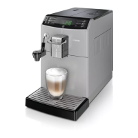
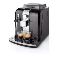
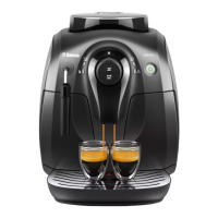
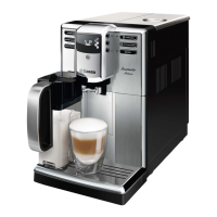
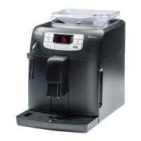
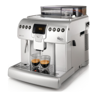
Identifies and illustrates the external components of the coffee machine.

1.7. Internal Machine Parts

Identifies and illustrates the internal components of the coffee machine.

Chapter 2: Technical Specifications

2.1. Technical Specifications

Details power supply, dimensions, weight, and technical parameters.

2.2. Machine Parameters and Performance

Specifies product quantities, rinse cycles, and descaling frequency.

2.3. Specification for Coffee Product Temperature Measurement

Provides guidelines for measuring coffee temperature under controlled conditions.

2.3.1. Specification for Milk Product Temperature Measurement

Details how to measure milk temperature and cream height for milk products.

Chapter 3: User Instructions

3.1. Customer and Programming Menu

Explains the functions of the buttons and navigation for user menus.

3.2. Machine Indications

Describes various machine messages and their meanings for user guidance.

3.3. Operation, Cleaning and Maintenance

Covers basic operation, cleaning procedures, and maintenance schedules.

Chapter 4: Operating Logic

4.1. Water Circuit

Illustrates the flow of water and steam through the machine's circuits.

4.2. Frother Unit Valve Assembly

Explains the functions of the frother unit valve assembly.

4.3. Cappuccino Maker Assembly

Details the components of the cappuccino maker assembly.

4.4. Relief Valve

Describes the function and operation of the relief valve.

4.5. Coffee Cycle

Outlines the sequence of operations during a coffee brewing cycle.

4.6. Single Microswitch

Explains the role of the single microswitch in the gear motor operation.

4.7. Temperature Sensor (Adjustment)

Details the temperature sensor's function and adjustment table.

4.8. Water Level Detection (Water Tank)

Explains how the water level sensor monitors the water tank status.

4.9. Descaling Request

Describes how the machine indicates the need for descaling or filter replacement.

4.10. Water Filter

Explains the function and lifespan of the water filter.

Chapter 5: Troubleshooting

5.1. Test Mode

Instructions on how to enter and navigate the machine's test mode.

5.2. Diagnostics Mode

Guide to entering and using the diagnostics mode for system checks.

5.3. Error Messages

Lists and describes common error codes and their meanings.

Chapter 6: Servicing and Maintenance

6.1. Repair Flow

Outlines the step-by-step process for repairing the coffee machine.

Chapter 7: Disassembly

7.1. Outer Elements

Detailed instructions for removing external parts of the machine.

7.2. Coffee Grinder

Step-by-step guide to disassembling the coffee grinder unit.

7.3. Grinder Blades

Procedures for removing, replacing, and adjusting the grinder blades.

7.4. Coffee Grinder Motor

Instructions for removing and replacing the coffee grinder motor.

7.5. Doser Hatch, Coil and Microswitch

Steps for accessing and removing the doser hatch, coil, and microswitch.

7.6. Doser Hopper

Guide to the removal of the doser hopper.

7.7. Coffee Boiler and Steam Boiler

Procedures for safely removing the coffee and steam boilers.

7.8. Boiler Pin

Instructions for removing the boiler pin cover and associated components.

7.9. Coffee Pump and Steam Pump

Steps for removing the coffee and steam pumps.

7.10. Flow Meter

Instructions for removing the flow meter.

7.11. Gear Motor

Procedures for removing the gear motor assembly.

7.12. Relief Valve

Steps for removing the relief valve.

7.13. Solenoid Valve Assembly

Instructions for removing the solenoid valve assembly.

7.14. Steam Pipe Assembly

Procedures for removing the steam pipe assembly.

7.15. Dispenser Assembly

Instructions for removing the dispenser assembly.

7.16. Power Board

Steps for removing the power board.

7.17. Display, Keypads and Control Board

Instructions for removing the display, keypads, and control board.

7.18. Fitting and Removing Oetiker Clamps

Guide to fitting and removing Oetiker clamps.

Chapter 8: Notes

Chapter 9: Water Circuit Diagram

Chapter 10: Electrical Diagram

Related product manuals