UM10155_2 © Koninklijke Philips Electronics N.V. 2006. All rights reserved.
User manual Rev. 02 — 5 September 2006 9 of 12
Philips Semiconductors
UM10155
Discrete Class D High Power Audio Amplifier
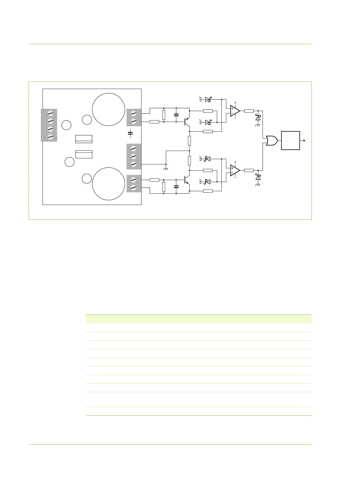
6.2 Short-circuit and overcurrent protection
The ‘Short-circuit and overcurrent protection’ circuit must be used together with the
‘Electronic enabling/disabling’ circuit.
The output pins of IC1 and IC2 produce a HIGH logic level pulse when overcurrent is
detected in either the low side MOSFET (Q13 on the Demonstrator Board) and high side
MOSFET (Q14 on the Demonstrator Board) respectively. The two signals are combined
through the IC3 OR-gate. The resulting signal must be processed in the ‘µP or other logic’
block. One of the simplest solutions would be a latch circuit, which on a high pulse forces
the output go low. This causes the ‘Electronic enabling/disabling circuit’ to disable the
amplifier. Through manual intervention and/or after a certain while, the latch should be
reset to a HIGH logic level, which in turn re-enables the amplifier.
Fig 9. Short-circuit and overcurrent protection
001aaf156
J3
J4
J5
J6
J10
J11
J8
J9
J7
J1
J2
C5
class D amp.
version 1.00
international
patent
WO 03/090343
PHILIPS
Q14
Q13
C7
+
+
+
+
+
+
C14
C11
C17
C15
R4
R3
R6
R5
R8
R9
D1
D3
R12
D6
R7
D2
R11
D4
R10
IC1
IC3
IC2
D5
Q1
Q2
C2
R1
R2 C1
L1
C19
µP OR
OTHER
LOGIC
to enabling/
disabling circuit
Table 3. Components
Component Value
R1, R4 270 Ω
R2, R3 4.7 kΩ
R5, R6, R7, R8, R9, R10, R11, R12 10 kΩ
C1, C2 4.7 nF
D1, D5 Philips PDZ10B
D2, D3, D4, D6 Philips PDZ5.1B
Q1 Philips BC846
Q2 Philips BC856
IC1, IC2 Fast operational amplifier; feed with +12 V and
−12 V supplies
IC3 Philips HEF4071; feed with 5 V