EasyManua.ls Logo

Philips TDA6107AJF User Manual

Philips TDA6107AJF
16 pages
To Next Page IconTo Next Page
Page #1 background imageLoading...
Page #1 background image
1. General description
The TDA6107AJF contains three video output amplifiers which are intended to drive the
three cathodes of a color CRT. The device is contained in a plastic DIL-bent-SIL 9-pin
medium power (DBS9MPF) package, and uses high-voltage DMOS technology.
To obtain maximum performance, the amplifier should be used with black-current control.
2. Features
Typical bandwidth of 5.5 MHz for an output signal of 60 V (p-p)
High slew rate of 900 V/µs
No external components required
Very simple application
Single supply voltage of 200 V
Internal reference voltage of 2.5 V
Fixed gain of 81
Black-Current Stabilization (BCS) circuit with voltage window from 1.8 V to 6 V and
current window from +100 µA to 10 mA
Thermal protection
Internal protection against positive flashover discharges appearing on the CRT
3. Ordering information
TDA6107AJF
Triple video output amplifier
Rev. 02 — 28 April 2005 Product data sheet
Table 1: Ordering information
Type number Package
Name Description Version
TDA6107AJF DBS9MPF plastic DIL-bent-SIL medium power package with fin; 9 leads SOT111-1
Question and Answer IconNeed help?

Do you have a question about the Philips TDA6107AJF and is the answer not in the manual?

Philips TDA6107AJF Specifications

General IconGeneral
TypeVideo Output Amplifier
Supply Voltage200 V
Heater Voltage6.3 V
ApplicationCRT Display
Mounting TypeThrough Hole

Summary

General Description

Features

Ordering Information

Block Diagram

Pinning Information

5.1 Pinning

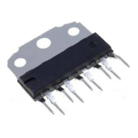
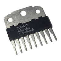
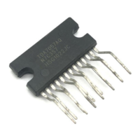
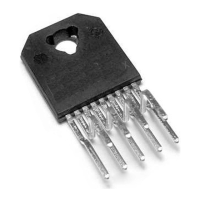
Overview of the physical pin arrangement for the TDA6107AJF integrated circuit.

5.2 Pin Description

Detailed explanation of the function and connection for each pin of the TDA6107AJF.

Internal Circuitry

Limiting Values

Thermal Characteristics

8.1 Thermal Protection

Description of the integrated circuit's thermal protection mechanism and its effect on performance.

Characteristics

Application Information

10.1 Cathode Output

Details on protection mechanisms for cathode outputs against peak currents during high and low resistance flashes.

10.2 Flashover Protection

Information on integrated protection diodes against CRT flashover discharges clamping cathode output voltage.

10.3 Switch-off Behavior

Explanation of the controllable switch-off behavior of the TDA6107AJF at various power supply voltages.

10.4 Bandwidth

Discussion on how flash resistor addition affects bandwidth and rise/fall times.

10.5 Dissipation

Analysis of static and dynamic power dissipation in the TDA6107AJF, including relevant formulas.

Test Information

11.1 Quality Information

Statement on the applicability of the General Quality Specification for Integrated Circuits.

Package Outline

Handling Information

Soldering

14.1 Introduction to Soldering Through-Hole Mount Packages

Overview of soldering methods for through-hole mount IC packages, focusing on wave soldering.

14.2 Soldering by Dipping or by Solder Wave

Details on wave soldering process, including dwell times and temperature considerations for lead-free pastes.

14.3 Manual Soldering

Guidelines for manual soldering techniques, specifying iron temperature and contact time limits.

14.4 Package Related Soldering Information

Suitability of different package types for dipping and wave soldering methods.

Revision History

Data Sheet Status

Definitions

Disclaimers

Contact Information

Related product manuals