Go to cover page
109B6 CRT
Repair Flow Chart
82
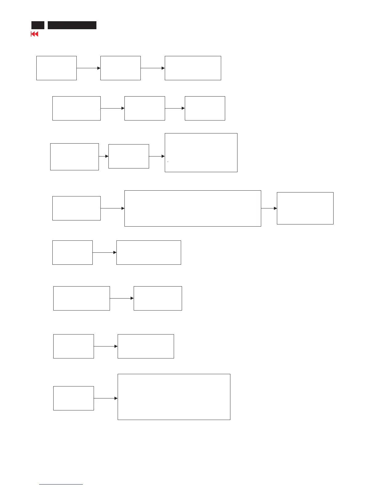
F. TDA4841
Check List
Basic check
Vcc > 9V
during startup
Vcc=pin9=pin10=12V
gnd =pin7=pin25=0v
1. HFLB
(from H.defl)
if no exist
pin16
CLBL=hi
2. Xray(Ground)
(Active LOT pin 12,
13to7411 pin1
if active
floating ----->7671
floating ----->7672
floating ----->5681 pin2
floating ----->5681 pin4
3.4.5.6B+ control
a pin3 amplify pin5 and it compare to pin4
b. pin4 generate the saw_tooth wave
c. pin5 input voltage for the square output waveform
d. pin6 pwm output to 7617&7618 base
inhibit pin6 output
if pin3 is pulled to
ground by 7505
8.HDRV
to H_deflection.
7606 base
12,13 Vout1/Vout2
differential input
to 7401 pin 1,7
14,15
Vsync,Hsync
the input sync from
cpu pin 33, 34
16. CLBL
Vertical blank will be activated = hi
1.pin30 = softstart pll2 = 0V
2.pin26 =pll1 is unlock in searching mode
3.pin1 = HFLB no exist
4.pin10 =Vcc<9V