Do you have a question about the Philips VL1000 TS and is the answer not in the manual?
Contact details for warranty claims and customer support.
Steps for obtaining and processing a Return Material Authorization for service.
List of manual revisions and their corresponding dates.
Statement regarding compliance with FCC rules for digital devices.
Declaration of product compliance with relevant safety and EMC directives.
Explanation of safety symbols and general warnings.
Instructions for continued protection against fire hazards.
Instructions for continued protection against electrical shock.
Manual is confidential property; unauthorized use is prohibited.
Purpose, scope, and intended audience of the manual.
Contact details for Vari-Lite customer service and technical support.
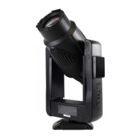
Overview of standard and model-specific features of the VL1000 ERS Luminaire.
Detailed breakdown of external and internal luminaire components.
Explanation of how the luminaire functions, including diagrams.
List of common features across all VL1000 ERS luminaire models.
Features unique to specific VL1000 models (TS, TI, AS, AI).
Illustration and identification of external parts and controls.
Major sub-assemblies located within the luminaire head.
Major sub-assemblies located within the luminaire yoke.
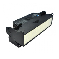
External ballast unit for arc models, including its components.
On-board IGBT dimmer for incandescent dimmer models.
Overview of how the incandescent source luminaire operates.
Block diagram for incandescent models without on-board dimmer.
Cable routing diagram for incandescent models without on-board dimmer.
Block diagram for incandescent models with on-board dimmer.
Cable routing diagram for incandescent models with on-board dimmer.
Overview of how the arc source luminaire operates.
Block diagram for arc source luminaires.
Cable routing diagram for arc source luminaires.
Procedures for testing luminaire parameters and functions.
Standard procedures for maintaining the luminaire.
How to run self-tests on the luminaire.
How to disable pan/tilt functions for testing.
Step-by-step guide for replacing incandescent lamps.
Step-by-step guide for replacing arc lamps.
How to align the lamp for optimal beam irradiance.
Procedure for installing or removing accessory frames or top hats.
Steps to remove and reinstall the luminaire's front cover.
Steps to remove the rear head assembly for access.
Procedure for replacing gobos in the rotating gobo wheel.
Procedure to align the gobo index timing belt.
Steps to remove and replace the gobo wheel bulkhead.
Procedure to align gobo gears for correct gobo indexing.
Steps for replacing the shutter assembly.
Procedure for replacing shutter blades or the shutter rack.
Steps to remove and replace the edge, zoom, and color bulkhead.
Procedure for replacing the fan and temperature switch assembly.
Steps for replacing the beam-size iris assembly.
Procedure for replacing the ignitor PCB.
Steps to remove and replace the power supply unit.
Procedure for replacing the controller PCB.
Steps to remove and replace the tilt encoder PCB.
Procedure for replacing the tilt motor assembly.
Steps to remove and replace the pan motor assembly.
Procedure for replacing the DMX input PCB.
Instructions for cleaning optical components using isopropyl alcohol.
Hierarchical diagrams illustrating part relationships.
Illustrated breakdown of the luminaire's top section.
Illustrated breakdown of the luminaire's head section.
Illustrated breakdown of the luminaire's yoke assembly.
Illustrated breakdown of electronic PCBs and modules.
Illustrated breakdown of various cable assemblies.
Illustrated breakdown of the arc ballast unit.
Detailed part breakdown diagram for incandescent models.
Detailed part breakdown diagram for arc models.
List and identification of items included in the luminaire kit.
Identification and location of various labels on the luminaire.
Table listing part numbers for different VL1000 luminaire configurations.
Illustrated breakdown of the front head assembly.
Illustrated breakdown of the edge, zoom, dimmer, and color assembly.
Illustrated breakdown of the color changer assembly.
Illustrated breakdown of Lens #6, #7, and #8 assemblies.
Illustrated breakdown of the fan assembly.
Illustrated breakdown of Incandescent and Arc gobo wheel assemblies.
Illustrated breakdown of the temperature sensor electrical assembly.
Illustrated breakdown of the shutter with 6 rollers assembly.
Illustrated breakdown of the beam-size iris assembly.
Illustrated breakdown of the rear head assembly.
Illustrated breakdown of the back cap assembly.
Illustrated breakdown of the yoke legs assembly.
Illustrated breakdown of the tilt motor assembly.
Illustrated breakdown of inner and outer crossmember assemblies.
Illustrated breakdown of the pan motor assembly.
Illustrated breakdown of the pan tube assembly.
Illustrated breakdown of the DMX input PCB assembly.
Illustrated breakdown of the arc power input (pigtail) cable assembly.
Illustrated breakdown of the Pan EOT cable assembly.
Illustrated breakdown of the Tilt COT cable assembly.
Illustrated breakdown of the AC line input cable assembly.
Illustrated breakdown of the incandescent LVS AC input cable assembly.
Illustrated breakdown of the arc LVS AC input cable assembly.
Illustrated breakdown of the LVS chassis ground cable assembly.
Illustrated breakdown of the head to backcap ground cable assembly.
Illustrated breakdown of the yoke to head ground cable assembly.
Illustrated breakdown of the pan/tilt control cable assembly.
Illustrated breakdown of the ballast control link cable assembly.
Illustrated breakdown of the data I/O link cable assembly.
Illustrated breakdown of the LVS DC output cable assembly.
Illustrated breakdown of the incandescent power input cable assembly.
Illustrated breakdown of the arc power to ignitor cable assembly.
Illustrated breakdown of the shutter harness cable assembly.
Illustrated breakdown of the color, gobo, and lens harness cable assembly.
Illustrated breakdown of the dimmer to LVS cable assembly.
Illustrated breakdown of the dimmer to controller cable assembly.
Illustrated breakdown of the dimmer to lamp socket cable assembly.
Illustrated breakdown of the 575W ballast I/O cable assembly.
List of technical bulletins for the VL1000 ERS luminaire.
| Type | Moving Head |
|---|---|
| Color Mixing | CMY |
| Gobo Wheels | 2 |
| Iris | Yes |
| Focus | Motorized |
| Pan | 540° |
| Tilt | 270° |
| Color Temperature | 3200K |
| Input Voltage | 100-240V AC, 50/60Hz |
| Control | DMX |