EasyManua.ls Logo

Philips VR705/02 - Page 66

Philips VR705/02
86 pages
Print Icon
To Next Page IconTo Next Page
To Previous Page IconTo Previous Page
Loading...
4-2
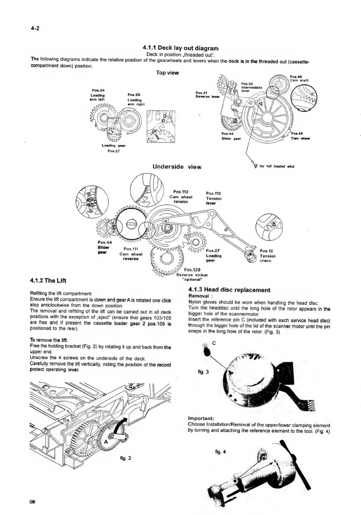
4.1.1
Deck
lay
out
diagram
Deck
in
position
,threaded
out".
The
following
diagrams
indicate
the
relative
position
of
the
gearwheels
and
levers
when
the
deck
is
in
the
threaded
out
(cassette-
compartment
down)
position.
Top
view
Pos.24
Loading
Pos.25
arm
left
Loading
arm
right
Loading
gear
Pos.27
Underside
view
Pos.111
Cam
wheel
reverse
4.1.2
The
Lift
Refitting
the
lift
compartment:
Ensure
the
lift
compartment
is
down
and
gear
A
is
rotated
one
click
stop
anticlockwise
from
the
down
position.
The
removal
and
refitting
of
the
lift
can
be
carried
out
in
all
deck
positions
with
the
exception
of
,eject"
(ensure
that
gears
103/105
are
free
and
if
present
the
cassette
loader
gear
2
pos.105
is
positioned
to
the
rear).
To
remove
the
lift:
Free
the
holding
bracket
(Fig.
2)
by
rotating
it
up
and
back
from
the
upper
end.
Unscrew
the
4
screws
on
the
underside
of
the
deck.
Carefully
remove
the
lift
vertically,
noting
the
position
of
the
record
protect
operating
lever.
Az
GB
Cam
wheel
Pos.46
Cam
shaft
Pos.31
Reverse
lever
a
Dove
Slider
gear
V
for
full
loaded
wind
Pos.112
Tension
lever
“optional”
4.1.3
Head
disc
replacement
Removal
:
Nylon
gloves
should
be
worn
when
handling
the
head
disc.
Turn
the
headdisc
until
the
long
hole
of
the
rotor
appears
in
the
bigger
hole
of
the
scannermotor
insert
the
reference
pin
C
(included
with
each
service
head
disc)
through
the
bigger
hole
of
the
lid
of
the
scanner
motor
until
the
pin
snaps
in
the
long
hole
of
the
rotor.
(Fig.
3)
Important:
Choose
Installation/Removal
of
the
upper/lower
clamping
element
by
turning
and
attaching
the
reference
element
to
the
tool.
(Fig.
4)