Do you have a question about the Philips VR730/07 and is the answer not in the manual?
Explains the functions of VCR and TV buttons on the remote control.
Details the power supply circuit and essential safety precautions.
Illustrates the overall wiring connections between major assemblies.
Details the pin functions and signal assignments for IC501.
Lists various capacitor part numbers and their applicability.
Lists various IC part numbers and their applicability.
Lists various transistor part numbers and their applicability.
Lists various parts of the deck mechanism.
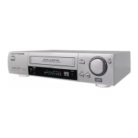
| Number of Heads | 4 |
|---|---|
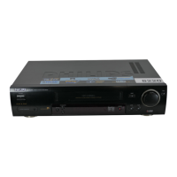
| TV Tuner | Yes |
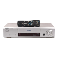
| Remote Control | Yes |
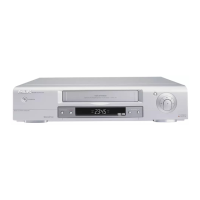
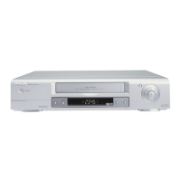
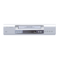
| Type | VCR |
| Recording Formats | VHS |
| Playback Formats | VHS |
| Inputs | Composite |
| Outputs | Composite |