EasyManua.ls Logo

Philips VR730/02 User Manual

Philips VR730/02
46 pages
To Next Page IconTo Next Page
Page #1 background imageLoading...
Page #1 background image
Service Manual
Service
Service
Service
Video Cassette Recorder
VR730/02/07/16/39
VR732
/02/16/39
Contents
Chapter
Adjustment Procedure
Schematic Diagrams and CBA's
Exploded Views
Mechanical and Electrical Parts Lists
Sec. 1:
Sec. 2:
Standard Maintenance
Mechanism Alignment Procedures
Disassembly / Assembly of Mechanism
Deck Exploded Views
Survey of versions:
/02 PAL B/G, VPS/PDC
/07 PAL I, Ireland
/16 PAL B/G, Spain
/39 SECAM L,L' & PAL B/G, I
/58 PAL/SECAM B/G, D/K
Safety regulations require that the set be restored to its original
condition and that parts which are identical with those specified
be used.
Published by BK 2002 Video Service Department Printed in Japan c
Copyright reserved Subject to modification GB 3103 785 22080
For technical data reference is made to the Service Manual of VR530/02/07/16
3103 785 21990.
The present Manual states only the differences.
Question and Answer IconNeed help?

Do you have a question about the Philips VR730/02 and is the answer not in the manual?

Philips VR730/02 Specifications

General IconGeneral
BrandPhilips
ModelVR730/02
CategoryVCR
LanguageEnglish

Summary

Service Manual Introduction and Device Overview

Versions and Identification

Details about different service manual versions and model identification.

Device Controls and Operation

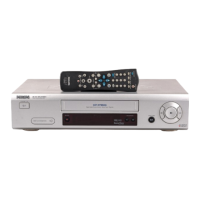
Descriptions of VCR and TV buttons on the remote control.

Device Physical Layout

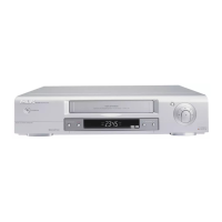
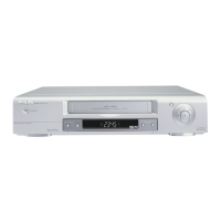
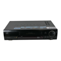
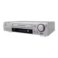
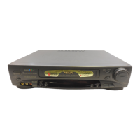
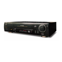
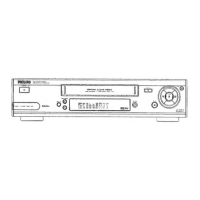
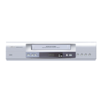
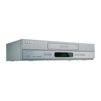
Identification of components on the front and connectors on the rear.

System Diagrams and Schematics

Block Diagrams Overview

Block diagrams for servo, video, audio, power, and system control.

Main Schematic Diagrams (1/6-6/6)

Comprehensive schematic diagrams covering all main circuit boards.

Specific Functional Schematics

Schematics for Function, AFV, VPS, and Jack circuit boards.

Wiring Diagram and IC Pinouts

Wiring diagram and IC501 pinout for system connectivity and control.

Parts Lists

Electrical Component Lists

Lists of capacitors, diodes, ICs, transistors, and resistors.

Mechanical Component List

List of all mechanical parts used in the device.

Assembly and Packing Information

Cabinet Assembly and Packing Details

Diagrams for cabinet assembly and product packing contents.

Related product manuals