EasyManua.ls Logo

Philips VR705/02 - Page 67

Philips VR705/02
86 pages
Print Icon
To Next Page IconTo Next Page
To Previous Page IconTo Previous Page
Loading...
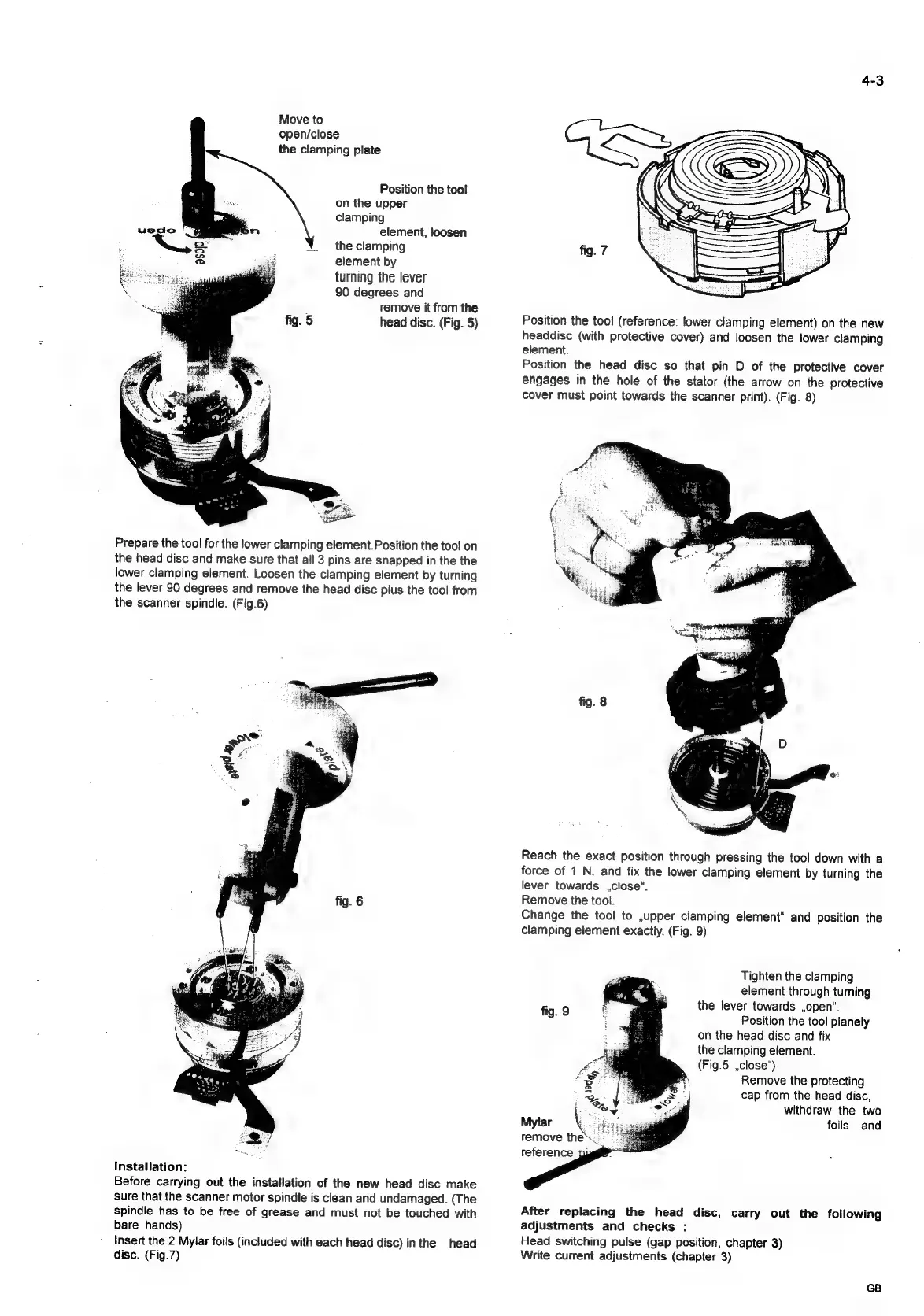
Move
to
open/close
the
clamping
plate
Position
the
tool
on
the
upper
clamping
element,
loosen
the
clamping
element
by
turning
the
lever
90
degrees
and
remove
it
from
the
head
disc.
(Fig.
5)
Prepare
the
tool
for
the
lower
clamping
element.Position
the
tool
on
the
head
disc
and
make
sure
that
all
3
pins
are
snapped
in
the
the
lower
clamping
element.
Loosen
the
clamping
element
by
turning
the
lever
90
degrees
and
remove
the
head
disc
plus
the
tool
from
the
scanner
spindle.
(Fig.6)
Installation:
Before
carrying
out
the
installation
of
the
new
head
disc
make
sure
that
the
scanner
motor
spindle
is
clean
and
undamaged.
(The
spindle
has
to
be
free
of
grease
and
must
not
be
touched
with
bare
hands)
Insert
the
2
Mylar
foils
(included
with
each
head
disc)
inthe
head
disc.
(Fig.7)
4-3
Position
the
tool
(reference:
lower
clamping
element)
on
the
new
headdisc
(with
protective
cover)
and
loosen
the
lower
clamping
element.
Position
the
head
disc
so
that
pin
D
of
the
protective
cover
engages
in
the
hole
of
the
stator
(the
arrow
on
the
protective
cover
must
point
towards
the
scanner
print).
(Fig.
8)
Reach
the
exact
position
through
pressing
the
tool
down
with
a
force
of
1
N.
and
fix
the
lower
clamping
element
by
turning
the
lever
towards
close".
Remove
the
tool.
Change
the
tool
to
,upper
clamping
element’
and
position
the
clamping
element
exactly.
(Fig.
9)
Tighten
the
clamping
element
through
turning
the
lever
towards
,open’.
Position
the
tool
planely
on
the
head
disc
and
fix
the
clamping
element.
(Fig.5
,close“)
Remove
the
protecting
cap
from
the
head
disc,
withdraw
the
two
foils
and
reference
pig
After
replacing
the
head
disc,
carry
out
the
following
adjustments
and
checks
:
Head
switching
pulse
(gap
position,
chapter
3)
Write
current
adjustments
(chapter
3)