EasyManua.ls Logo

Philips VR705/02 - Page 68

Philips VR705/02
86 pages
Print Icon
To Next Page IconTo Next Page
To Previous Page IconTo Previous Page
Loading...
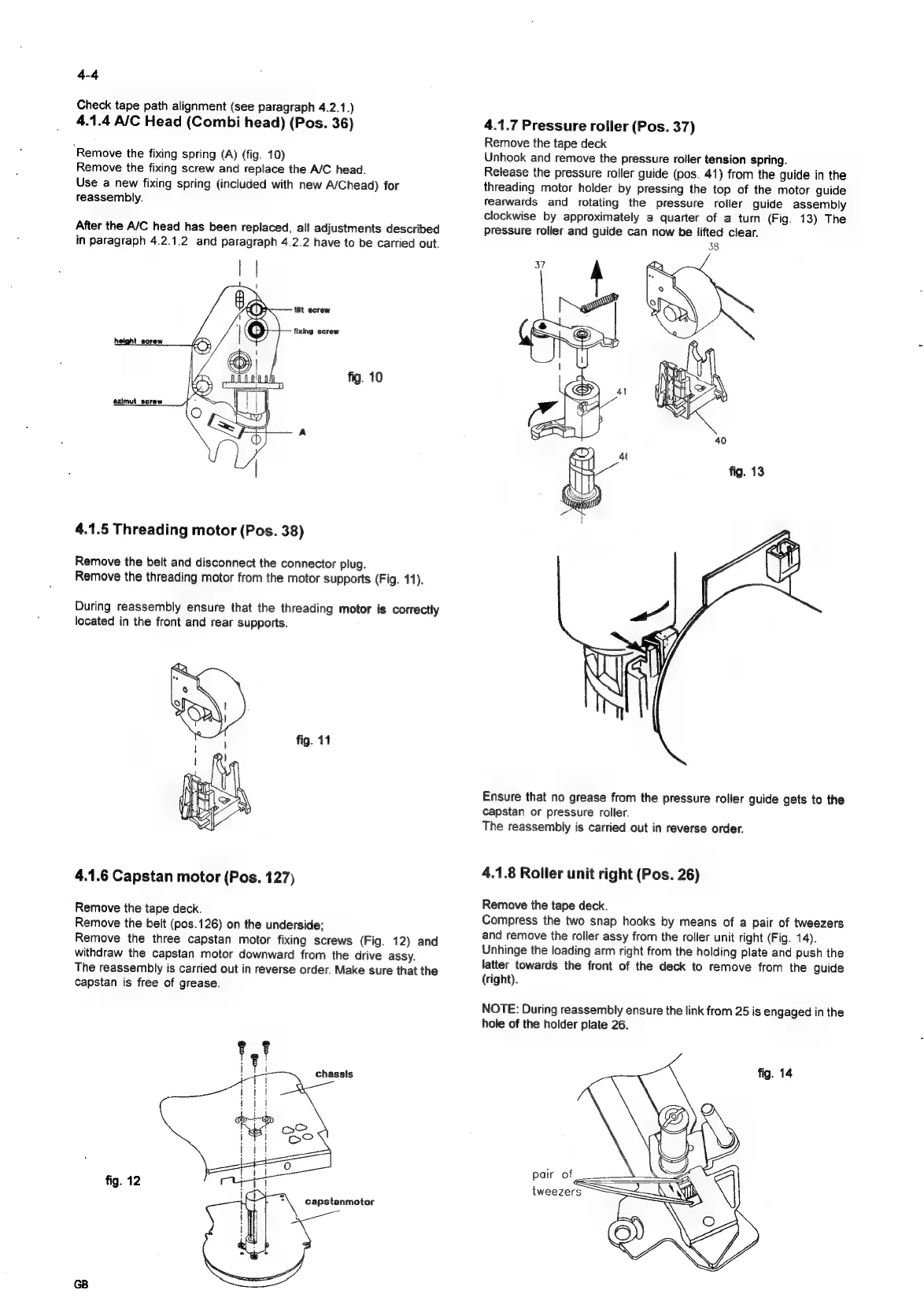
4-4
Check
tape
path
alignment
(see
paragraph
4.2.1.)
4.1.4
A/C
Head
(Combi
head)
(Pos.
36)
ā€˜Remove
the
fixing
spring
(A)
(fig.
10)
Remove
the
fixing
screw
and
replace
the
A/C
head.
Use
a
new
fixing
spring
(included
with
new
A/Chead)
for
reassembly.
After
the
A/C
head
has
been
replaced,
all
adjustments
described
in
paragraph
4.2.1.2
and
paragraph
4.2.2
have
to
be
carried
out.
tit
screw
tlxing
screw
fig.
10
4.1.5
Threading
motor
(Pos.
38)
Remove
the
belt
and
disconnect
the
connector
plug.
Remove
the
threading
motor
from
the
motor
supports
(Fig.
11).
During
reassembly
ensure
that
the
threading
motor
is
correctly
located
in
the
front
and
rear
supports.
fig.
11
4.1.6
Capstan
motor
(Pos.
127)
Remove
the
tape
deck.
Remove
the
belt
(pos.126)
on
the
underside;
Remove
the
three
capstan
motor
fixing
screws
(Fig.
12)
and
withdraw
the
capstan
motor
downward
from
the
drive
assy.
The
reassembly
is
carried
out
in
reverse
order.
Make
sure
that
the
capstan
is
free
of
grease.
chassis
fig.
12
4.1.7
Pressure
roller
(Pos.
37)
Remove
the
tape
deck
Unhook
and
remove
the
pressure
roller
tension
spring.
Release
the
pressure
roller
guide
(pos.
41)
from
the
guide
in
the
threading
motor
holder
by
pressing
the
top
of
the
motor
guide
rearwards
and
rotating
the
pressure
roller
guide
assembly
clockwise
by
approximately
a
quarter
of a
turn
(Fig.
13)
The
pressure
roller
and
guide
can
now
be
lifted
clear.
38
Ensure
that
no
grease
from
the
pressure
roller
guide
gets
to
the
capstan
or
pressure
roller.
The
reassembly
is
carried
out
in
reverse
order.
4.1.8
Roller
unit
right
(Pos.
26)
Remove
the
tape
deck.
Compress
the
two
snap
hooks
by
means
of
a
pair
of
tweezers
and
remove
the
roller
assy
from
the
roller
unit
right
(Fig.
14).
Unhinge
the
loading
arm
right
from
the
holding
plate
and
push
the
latter
towards
the
front
of
the
deck
to
remove
from
the
guide
(right).
NOTE:
During
reassembly
ensure
the
link
from
25
is
engaged
in
the
hole
of
the
holder
plate
26.
pair
of
tweezer: