EasyManua.ls Logo

Philips VR705/02 - Page 70

Philips VR705/02
86 pages
Print Icon
To Next Page IconTo Next Page
To Previous Page IconTo Previous Page
Loading...
4-6
By
means
of
the
tilt
angle
adjusting
screw
move
the
tape
until
the
lower
edge
just
touches
the
tape
guide
A1
(see
Fig.
19)
the
tape
must
not
be
distorted
at
the
lower
edge
(by
pressing
onto
guide).
Adjustment
of
the
azimuth
angle
and
the
head
height
Connect
an
oscilloscope
to
the
linear
Audio
output.
Play
the
section
of
the
test
cassette
with
the
audio
signal
400
Hz.
Adjust
for
maximum
output
voltage
by
means
of
the
height
adjustment
screw
Play
the
section
of
the
test
cassette
with
the
audio
signal
8
kHz.
Adjust
to
maximum
output
voltage
by
means
of
the
azimuth
adjustment
screw
(Fig.
19).
If
necessary,
repeat
this
procedure
Check
the
tilt
angle
adjustment
If
the
tape
path
was
completely
out
of
adjustment
or
if
several
components
in
the
tape
path
have
been
replaced,
it
is
possible,
that
the
adjustments
described
in
paragraph
4.2.1.1
and
paragraph
4.2.1.2
have
to
be
repeated
several
times.
4.2.2
Adjustment
of
the
horizontal
distance
(x-distance)
Before
this
adjustment
is
carried
out,
insert
the
test
cassette
(start
from
Eject
position).
Call
the
service
test
program
(tracking
value
will
take
up
its
nominal
position)
and
press
the
,play"
button.
Playback
the
black/white
part
of
the
test
cassette.)
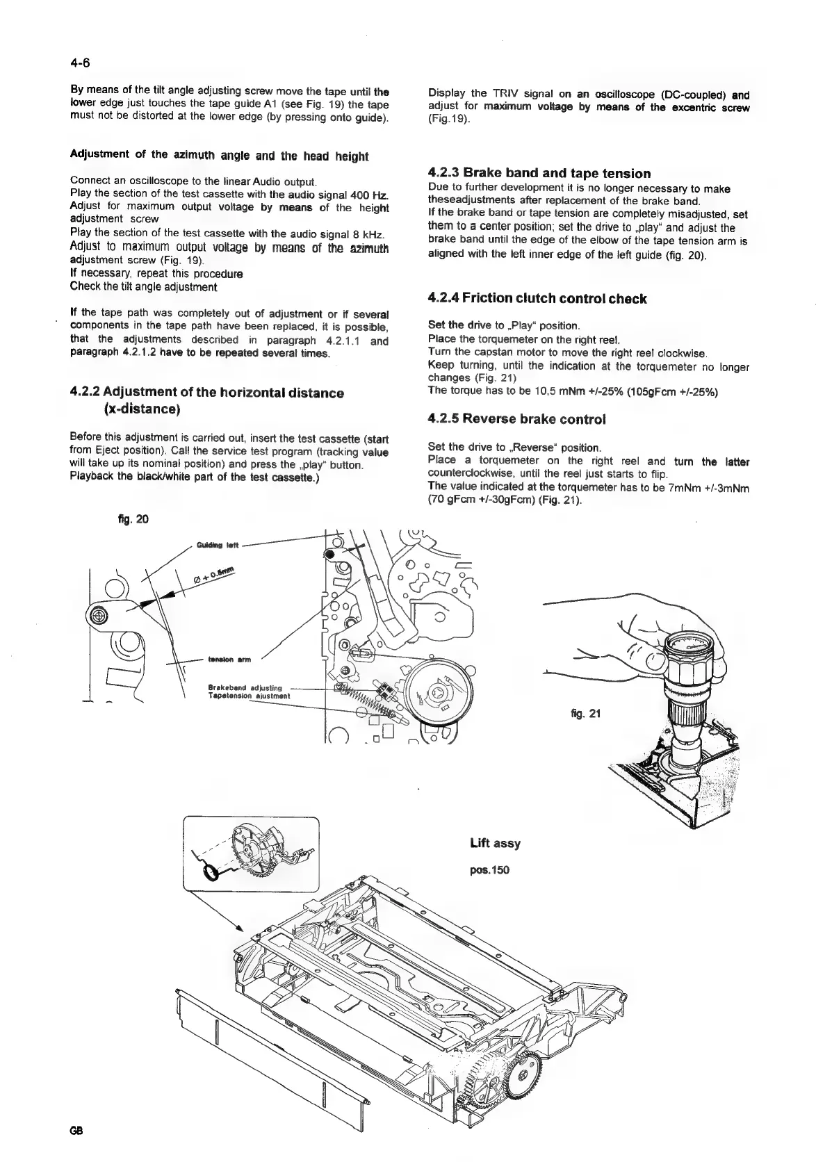
fig.
20
Guiding
teft
0
4
08S
tension
arm
Brakeband
adjusting
Tapetension
ajustment
Display
the
TRIV
signal
on
an
oscilloscope
(DC-coupled)
and
adjust
for
maximum
voliage
by
means
of
the
excentric
screw
(Fig.19).
4.2.3
Brake
band
and
tape
tension
Due
to
further
development
it
is
no
longer
necessary
to
make
theseadjustments
after
replacement
of
the
brake
band.
If
the
brake
band
or
tape
tension
are
completely
misadjusted,
set
them
to
a
center
position;
set
the
drive
to
,play“
and
adjust
the
brake
band
until
the
edge
of
the
elbow
of
the
tape
tension
arm
is
aligned
with
the
left
inner
edge
of
the
left
guide
(fig.
20).
4.2.4
Friction
clutch
control
check
Set
the
drive
to
,Play“
position.
Place
the
torquemeter
on
the
right
reel.
Turn
the
capstan
motor
to
move
the
right
reel
clockwise.
Keep
turning,
until
the
indication
at
the
torquemeter
no
longer
changes
(Fig.
21)
The
torque
has
to
be
10,5
mNm
+/-25%
(105gFcm
+/-25%)
4.2.5
Reverse
brake
control
Set
the
drive
to
,Reverse"
position.
Place
a
torquemeter
on
the
right
reel
and
turn
the
latter
counterclockwise,
until
the
reel
just
starts
to
flip.
The
value
indicated
at
the
torquemeter
has
to
be
7mNm
+/-3mNm
(70
gFcm
+/-30gFcm)
(Fig.
21).
Lift
assy
pos.150