Appendix
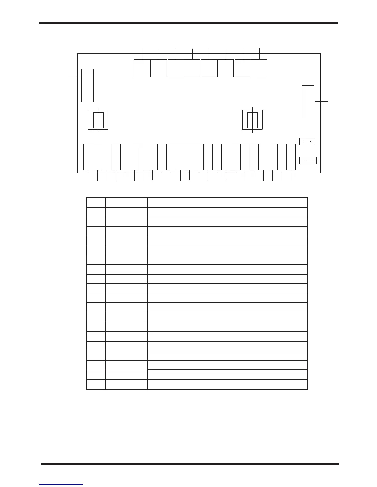
Connections explanation:
1
2
3
4
No.
Symbol
Meaning
System1 mangtic valve outlet(220-230VAC)
System 2 economizer outlet temp.failure(input)
7
8
9
10
11
12
13
14
15
5
6
Ambient temp.(input)
RO02
RO04
RO03
RO01
AI03 GND
AI04 GND
AI05 GND
AI06 GND
AI07 GND
AI08 GND
AI09 GND
System 2 exhaust temp.(input)
System 1 exhaust temp.(input)
System 2 economizer inlet temp.failure(input)
System 1 economizer inlet temp.failure(input)
System 1 economizer outlet temp.failure(input)
Wire controller
System 2 economizer outlet temp.failure(input)
16
17
18
19
Ambient temp.(input)
NET GND 12V
DI01 GND
AI01 GND
AI02 GND
AI03 GND
AI04 GND
AI05 GND
AI06 GND
AI07 GND
AI08 GND
AI09 GND
System 2 exhaust temp.(input)
System 1 exhaust temp.(input)
System 2 economizer inlet temp.failure(input)
System 1 economizer inlet temp.failure(input)
System 1 economizer outlet temp.failure(input)
System 2 anti-freeze temp.(input)
System 1 anti-freeze temp.(input)
Mode/conmunication
System2 mangtic valve outlet(220-230VAC)
System1 alert outlet(220-230VAC)
System2 alert outlet(220-230VAC)
CC01
CC02
CC03
CC04
System1 mangtic valve inlet(220-230VAC)
System2 mangtic valve inlet(220-230VAC)
System1 alert inlet(220-230VAC)
System2 alert inlet(220-230VAC)
9
10
11
12
13
14
15
CN2
BHB10
CN3
RLY1RLY2RLY3RLY4
CN5
CN6
12V
NET
GND
DI01
AI01
AI02
AI03
AI04
AI05
AI06
AI07
AI08
CT1 CT2
CN4
GND
GND
GND
GND
GND
GND
GND
GND
GND
CC01
AI09
GND
CC02 RO01 RO02RO03RO04 CC03 CC04
Appendix 7、Connection of PCB illustration
2.SYSB malfunction Table
The common failure cause and solution.
System 2 economizer
outlet temp.failure
System 1 anti-freeze protection
System 2 anti-freeze protection
Malfunction
Ambient temp.sensor failure
Communication failure
System 1 exhaust temp.failure
System 2 exhaust temp.failure
System 1 anti-freeze temp.failure
System 2 anti-freeze temp.failure
System 1 economizer
inlet temp.failure
System 2 economizer
inlet temp.failure
System 1 economizer
outlet temp.failure
P202
P29
Display
P04
E08
P181
P281
E171
E271
P101
P201
P102
Water flow volume not enough
Canse
Communication failure between
remote wire controller and main board
The sensor is open or short circuit
Solution
Check the wire connection between
remote wire controller and main board
Check or change the sensor
Check the flow volume,water
system is jammed or not
System 1 current protection
E151
Current through compressor too heavy
Check through the power supply for
compressor or short circuit
E251
Current through compressor too heavy
Water flow volume not enough
Check the flow volume,water
system is jammed or not
The sensor is open or short circuit
Check or change the sensor
The sensor is open or short circuit
Check or change the sensor
The sensor is open or short circuit
Check or change the sensor
The sensor is open or short circuit
Check or change the sensor
The sensor is open or short circuit
Check or change the sensor
The sensor is open or short circuit
Check or change the sensor
The sensor is open or short circuit
Check or change the sensor
The sensor is open or short circuit
Check or change the sensor
System 2 current protection
Check through the power supply for
compressor or short circuit
P19
P182
Compressor exhaust temp.too high
System 1 exhaust high
temp.protection
Check through the refrigerant system
P282
System 2 exhaust high
temp.protection
Compressor exhaust temp.too high Check through the refrigerant system
Appendix
26
27