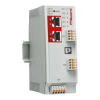
Operating elements and LEDs
8334_en_02 PHOENIX CONTACT 15
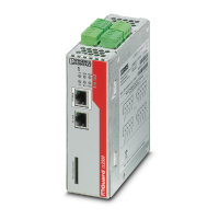
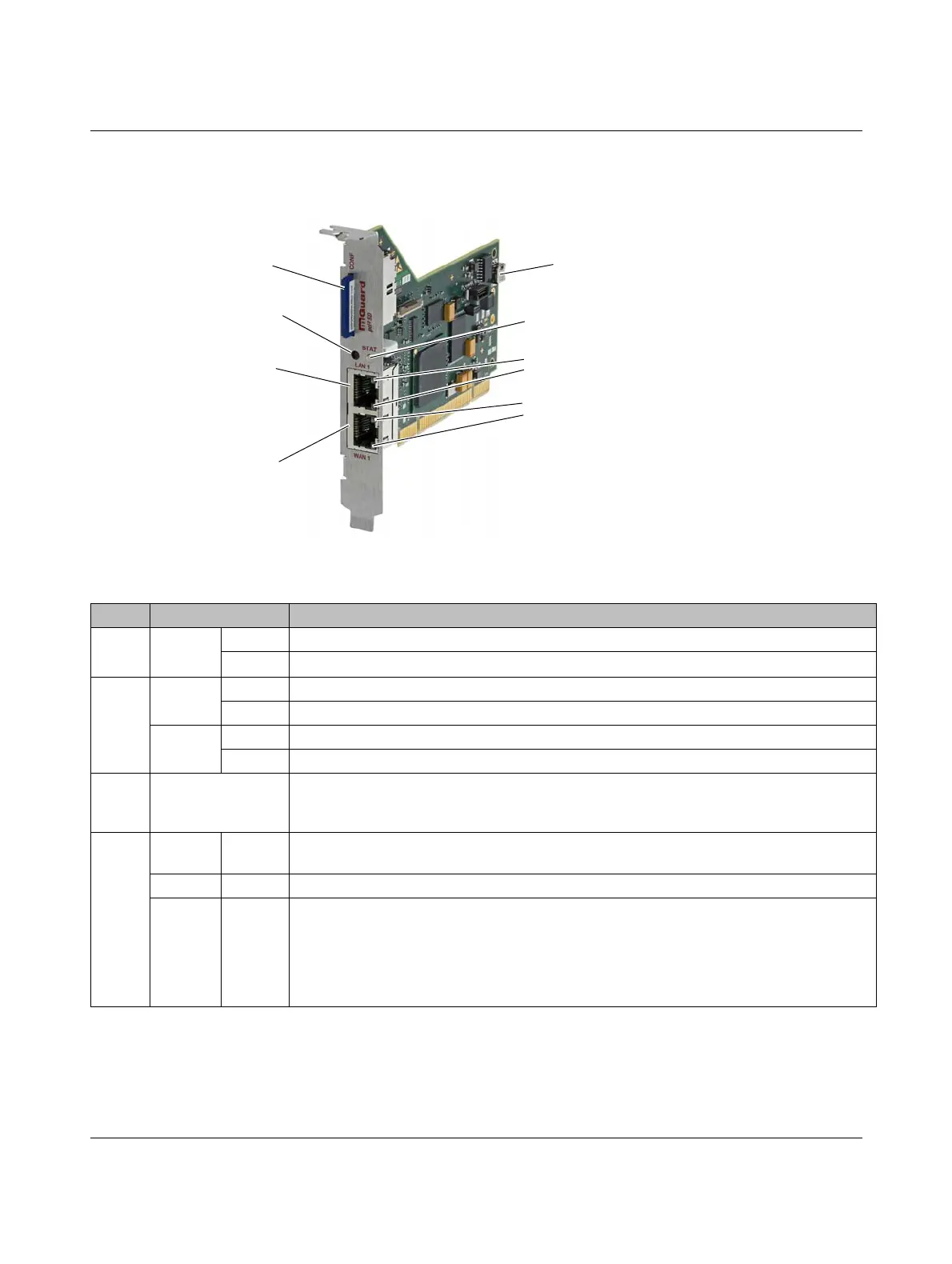
2.3 FL MGUARD PCI4000
Figure 2-3 Operating elements and LEDs on the FL MGUARD PCI4000
WAN 1 LED
SD card slot (configuration
memory)
Reset button
RJ45 socket (LAN 1) for
connecting the internal
network
RJ45 socket (WAN 1) for
connecting the external
network/Internet
LAN 1 LED
Battery (can be replaced)
STAT LED
LAN 2 LED
WAN 1 LED
Table 2-3 LEDs on the FL MGUARD PCI4000 SD
LEDs State Meaning
WAN 1
LAN 1
Green ON Full duplex
OFF Half duplex
WAN 2
LAN 2
Yellow ON 10 Mbps
Flashing 10 Mbps, data transmission active
Green ON 100 Mbps
Flashing 100 Mbps, data transmission active
LAN 1
LAN 2
WAN 1
Various LED light
codes
Recovery procedure/flashing
See “NOTE: Restart, recovery procedure, and flashing the firmware” on page 323
STAT Red/
green
Flashing Boot process. When the device has just been connected to the power supply. After a few
seconds, this LED changes to the heartbeat state.
Green Flashing Heartbeat. The FL MGUARD is connected correctly and ready to operate.
Red Flashing System error. Restart the device.
• Press the Reset button (for 1.5 seconds).
• Alternatively, briefly disconnect the device power supply and then connect it again.
If the error is still present, start the recovery procedure (see “Performing a recovery
procedure” on page 324) or contact your dealer.
 Loading...