Description of I/O extension modules
105542_en_05 PHOENIX CONTACT 89 / 198
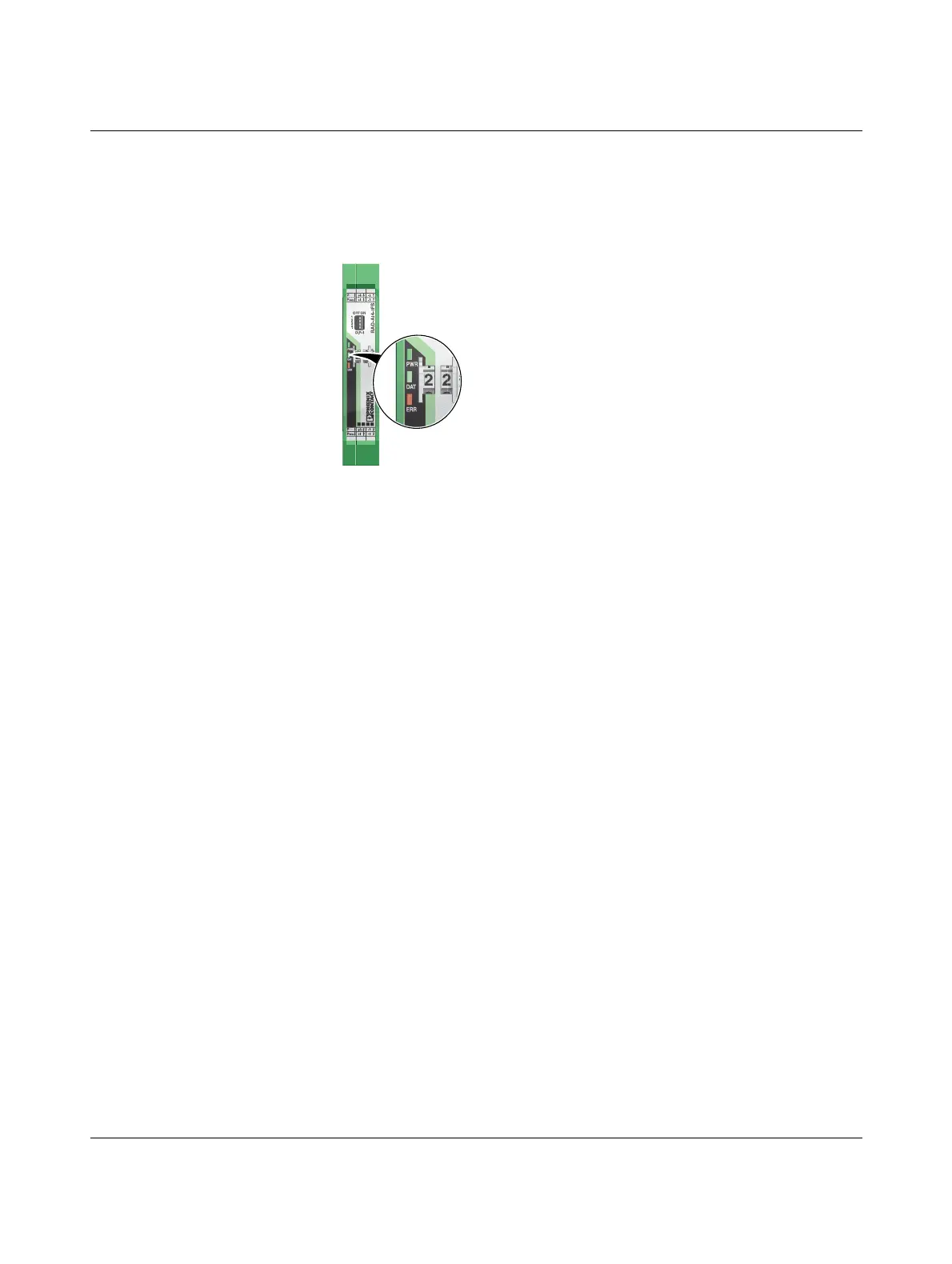
7.1.4 Diagnostic LEDs
The RAD-AI4-IFS I/O extension module uses a total of three LEDs to indicate the operating
states.
Figure 7-4 Diagnostic LEDs of the RAD-AI4-IFS
PWR LED
The green PWR LED indicates the status of the supply voltage.
DAT LED
The green DAT LED indicates the status of bus communication.
ERR LED
The red ERR LED indicates the error status.
Off No supply voltage
On Supply voltage OK
Off No communication
Flashing Configuration and addressing mode
On Cyclic data communication
Off No error
Flashing
Slow (1.4 Hz) I/O MAP address changed
Fast (2.8 Hz) No bus communication
On Critical internal error
-I4+I4PWR4
-I3+I3PWR3
-I2+I2PWR2
-I1+I1PWR1
OFF ON
DIP-1
1
2
3
4
PWR
DAT
ERR
44
3WR3
22
1WR1
 Loading...

