Description of I/O extension modules
105542_en_05 PHOENIX CONTACT 101 / 198
7.3.4 Diagnostic LEDs
The RAD-AO4-IFS I/O extension module uses a total of three LEDs to indicate the operating
states.
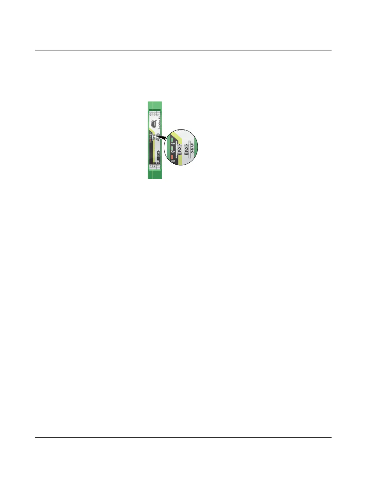
Figure 7-17 Diagnostic LEDs of the RAD-AO4-IFS
PWR LED
The green PWR LED indicates the status of the supply voltage.
DAT LED
The green DAT LED indicates the status of bus communication.
ERR LED
The red ERR LED indicates the error status, e.g., if a corresponding input module has not
been found.
Off No supply voltage
On Supply voltage OK
Off No communication
Flashing Configuration and addressing mode
On Cyclic data communication
Off No error
Flashing
Slow (1.4 Hz) I/O MAP address changed
Fast (2.8 Hz) Wireless module in I/O data mode
– Missing input module
– No bus communication
Wireless module in PLC / Modbus/RTU mode
– No Modbus communication (safe state of outputs, depending
on DIP switch setting)
On Critical internal error
3
4U4
U3
I4
I3
1
2U2
U1
I2
I1
OFF ON
DIP-1
1
2
3
4
PWR
DAT
ERR
444
3
3
222
11

 Loading...

