RAD-...-IFS
114 / 198
PHOENIX CONTACT 105542_en_05
ERR LED
The red ERR LED indicates the error status, e.g., if a corresponding input module has not
been found.
DO1 ... DO4
The yellow DO1 ... DO4 LEDs indicate the state of the digital outputs.
7.6.5 Setting the I/O MAP address
Use the thumbwheel to set the I/O MAP address. The extension module in the Radioline
wireless system is addressed using the I/O MAP address. Addresses 01 ... 99 (maximum)
can be assigned for the I/O extension modules in the entire wireless network.
Process data in PLC / Modbus/RTU mode
The process image of the I/O extension module consists of two data words. For additional
information on the process data, please refer to Section “RAD-DOR4-IFS process data” on
page 75.
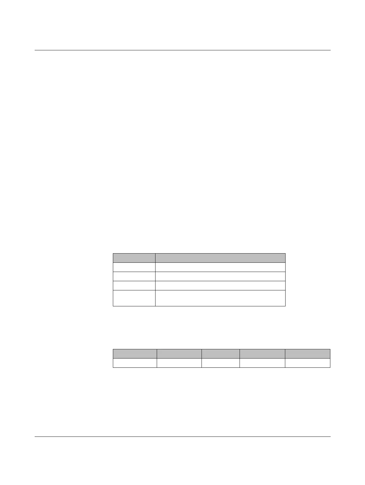
Off No error
Flashing
Slow (1.4 Hz) I/O MAP address changed
Fast (2.8 Hz) Wireless module in I/O data mode
– Missing input module
– No bus communication
Wireless module in PLC / Modbus/RTU mode
– No Modbus communication (safe state of outputs, depending
on DIP switch setting)
On Critical internal error
Table 7-11 Setting the I/O MAP address for the RAD-DOR4-IFS
Thumbwheel Description
01 ... 99 I/O MAP address
00 Delivery state
**, 1* ... 9* Setting not permitted
*1 ... *9 Interface system slave address, for use with other
interface system (IFS) master devices
I/O module Module type ID Register Address range Function code
RAD-DOR4-IFS 10
hex
02
hex
40xx0 ... 40xx1 fc 03, 16

 Loading...

