Installation
105542_en_05 PHOENIX CONTACT 21 / 198
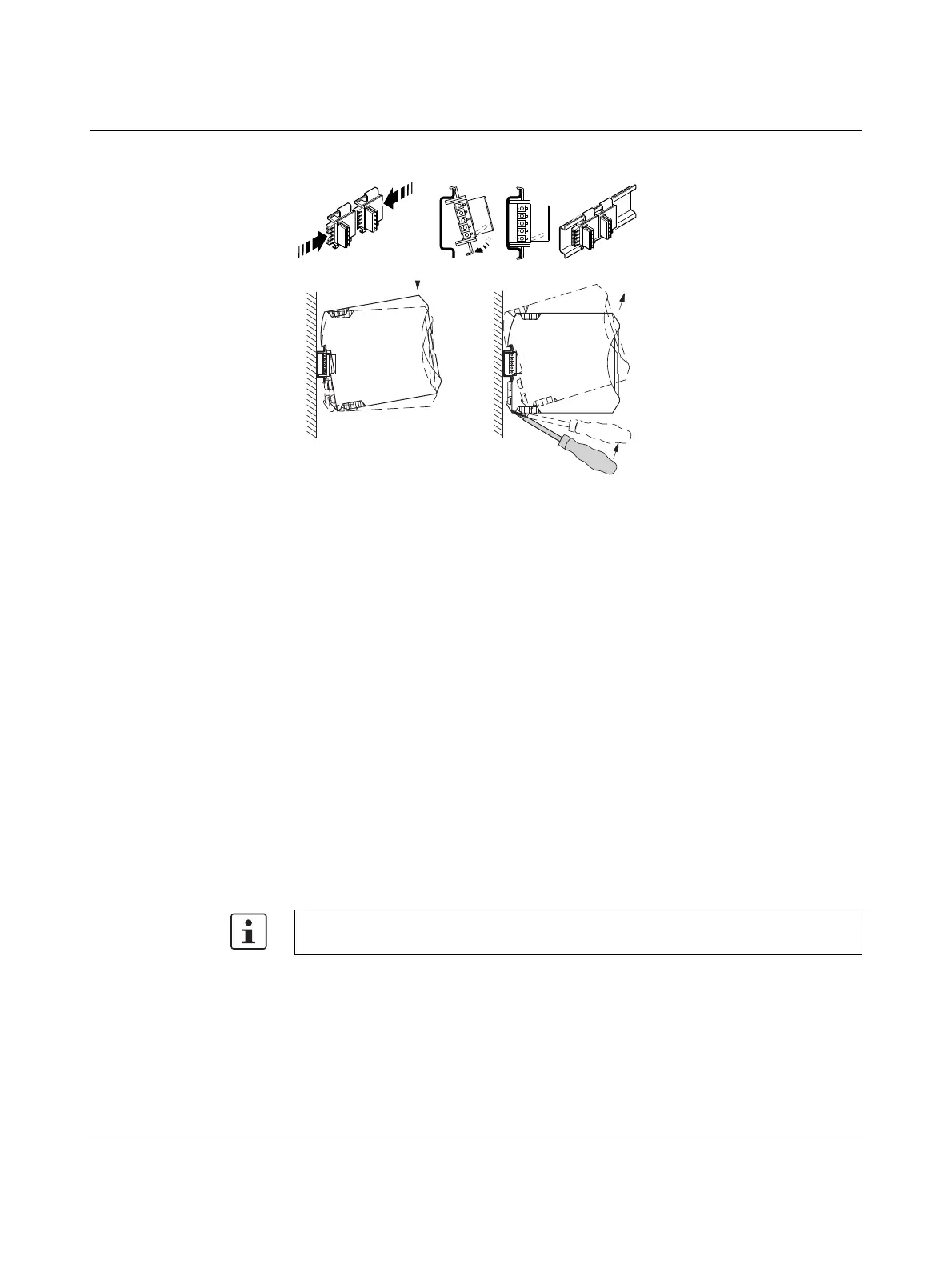
Figure 3-4 Mounting and removal
Mounting a connection station with DIN rail connectors:
• To form a connection station, connect the DIN rail connectors together.
• Push the connected DIN rail connectors onto the DIN rail.
• Place the device onto the DIN rail from above (see Figure 3-4, D). Make sure that the
device and DIN rail connector are aligned correctly.
• Holding the device by the housing cover, carefully push the device towards the mount-
ing surface so that the device bus connector is securely fixed onto the DIN rail connec-
tor.
• Once the snap-on foot snaps onto the DIN rail, check that it is fixed securely. The device
is only mechanically secured via the DIN rail.
• Connect the desired number of I/O extension modules to the wireless module via the
DIN rail connector.
• In order to meet the requirements for the protection class, install the device in suitable
housing.
• During startup, check that the device is operating, wired, and marked correctly.
• A connection between two DIN rail connectors can be established using MINI
COMBICON connectors:
– MC 1,5/5-ST-3,81 (socket, 1803604);
– IMC 1,5/5-ST-3,81 (pin, 1857919)
Removal
• Use a suitable screwdriver to release the locking mechanism on the snap-on foot of the
device (see Figure 3-4, E).
• Hold onto the device by the housing cover and carefully tilt it upwards.
• Carefully lift the device off the DIN rail connector and the DIN rail.
Device replacement is also possible during operation when outside the Ex area.

 Loading...

