©2010 Phoenix Controls Specifications subject to change without notice. Rev. 5/10 MKT-0266 MPC-1480 FAN STATIC RESET KIT—3 OF 12
INSTALLATION
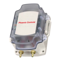
The Fan Static Reset kit comes complete with all the components and mounting hardware necessary for installation. The pressure
sensor mounts to the valve base channel and gets its power from the valve controller and connects to any available UI on the valve
controller. The pressure pickups are mounted upstream and downstream of the valve and connected using the two supplied sets of
silicon tubing and pressure dampers. Nylon wire ties and self-adhesive mounts may be used to secure the silicon tubing to the duct.
Mounting the sensor
The sensor is attached to a mounting bracket that can be mounted in several locations on the base channel depending on the size of
the valve, its actuator type and what options are installed. Two locations, opposite the electronics enclosure have existing holes and
are preferred for mounting the sensor (see 1 and 2 below). Two alternate locations, on opposite corners of the base channel (3 and 4
below) require the use of self-drilling, "Zip" screws. Use care when using the "Zip" screws so they do not pierce the valve body.
1
May be used if the preferred locations are obstructed by other components on the base channel
NOTE: Mount the sensor bracket using two screws in an orientation that allows access to the electrical connection port and
permits the enclosure door to open allowing access to the internal wire connections.
Guidelines for locating the pressure pickups
For stable and accurate readings the duct runs immediately upstream and downstream must be straight and free of any obstructions
such as bends, transitions, filters, dampers and coils. Per ANSI/ASHRAE 130-2008 Methods of Testing Air Terminal Units, the duct
immediately upstream and downstream of the valve must be uniform in shape with no obstructions for a minimum of 3.0
equivalent duct diameters upstream, and 3.5 equivalent duct diameters downstream of the valve. Anything less than the 3
uninterrupted duct diameters upstream and 3.5 diameters downstream is highly suspect and should not be used. The longer the
straight uninterrupted duct runs upstream and downstream of the valve, the better the flow profile and the more stable and accurate
the readings you will achieve.
Additionally, the pressure pickups must be a minimum of 1.5 equivalent duct diameters upstream and 2.5 equivalent duct
diameters downstream away from the valve. Any closer to the valve and turbulence from the valve components in the flow stream
will likely compromise the stability and accuracy of any readings. As a general rule, the area within a minimum of 1.5 equivalent
duct diameters downstream or upstream of any obstruction would be a poor location for the pressure pickup. The further away the
pressure pickups are located from the valve and any other obstruction, the more stable and accurate the readings will be.
Table 1: Sensor Mounting Location and Actuator Type
Number Location Type Valve Size Actuator Type
1PreferredAll All
2 Preferred All HiSEA and Pneumatic
3
Alternate
1
All All
4
Alternate
1
12" and 14" All
1
23
4
 Loading...