©2010 Phoenix Controls Specifications subject to change without notice. Rev. 5/10 MKT-0266 MPC-1480 FAN STATIC RESET KIT—7 OF 12
WIRING THE PRESSURE SENSOR
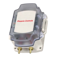
The pressure sensor is a 3-wire device; power, signal and circuit common. Three white crimp-on connectors are provided with the
kit and are used to connect the wires coming off of the sensor printed circuit board (PCB) with a 3-conductor cable (provided by
others) that terminates in the valve mounted controller enclosure. This cable leaves the sensor housing via the pre-drilled conduit
port opposite the pressure ports so no enclosure modifications are required in the field.
A 3-conductor cable must be run between the pressure sensor enclosure and the valve mounted controller enclosure. Wiring details
follow.
NOTE: Lead wire lengths will impact signal output/accuracy. Cable length should be limited to 5 to 10 feet (1.5 to 3 meters).
At the Sensor
• Red wire is for power
• White wire is for signal "+"
• Black wire is for circuit common
At the Celeris High-Speed Electric Controller
• FSR power wire terminates on TB4, Terminal 1 (L1)
• FSR signal "+" wire terminates on TB1, Terminals 1, 3 or 5 (+)
• FSR circuit common wire terminates on TB1, Terminals 2, 4 or 6 (-)
Celeris high-speed electric: any available UI (1, 2 or 3)
+ 1
- 2
UI1
TB1
-
4
5
+
UI3
UI2
3
+
-
6
-
8
DI1
+
7
L2
L1
GND
WHITE (SIGNAL)
BLACK (CIRCUIT COMMON)
RED (POWER)
TB4