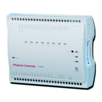
PROGRAMMABLE CONTROL MODULE: LONMARK
®
75 Discovery Way • Acton, MA 01720 • Tel (978) 795-1285 • Fax (978) 795-1111 • www.phoenixcontrols.com
©2009 Phoenix Controls. Specifications subject to change without notice. Rev. 11/11 MKT-0244 MPC-1673 PROGRAMMABLE CONTROL MODULE: LONMARK 1
General Specifications (continued)
• Clock: Real-time clock chip
1
• Battery (for clock only): CR2032 Lithium (for clock)
1
• Status indicator:
- Green LEDs: power status and LON TX
2
- Orange LEDs: service and LON RX
2
• Communication Jack: LON
®
audio jack mono 1/8" (3.5 mm)
1.
PCM200 and PCM201 do not have a clock function
2.
All except PCM200
Inputs/Outputs
Type and quantity of I/O are determined by model number. For
details on I/O, see the Selection Guide on pages 3 and 4.
Agency Compliance
Programmable Control Module (PCM)
Electromagnetic Compatibility:
CE: —Emission: EN61000-6-3: 2001; Generic standards
for residential, commercial and light-
industrial environments
—Immunity EN61000-6-1: 2001; Generic standards
for residential, commercial and light-
industrial environments
FCC: This device complies with part 15 of the FCC Rules.
Operation is subject to the following two conditions:
1. This device may not cause harmful interference.
2. This device must accept any interference received,
including interference that may cause undesired
operation.
Agency Approvals
UL Listed (CDN and US):
UL916 Energy management equipment
Material: UL94-5VA
The Phoenix Controls Programmable Control Module (PCM) series
provides a means of connecting additional inputs and outputs to the
Celeris
®
, Theris
®
and Traccel
®
room-level network and developing
custom control sequences to enhance the control functions already
provided. The PCM offers varying numbers of configurable input and
output connections, a graphical programming interface for developing
custom control applications. The PCM adds tremendous power and
flexibility to the Phoenix Controls environmental control system. The
graphical programming interface makes developing custom control
sequences simple and efficient.
FEATURES
• Interfaces with Celeris, Theris and Traccel room-level networks
• 4, 6, 10 and 12 universal inputs
• 6, 8 and 12 universal/digital outputs
• Graphical block-oriented programming
• DIN rail mounting (all but PCM200)
• Separable housing allows removal of controller from wiring base
SPECIFICATIONS
Enclosure
• ABS type PA-765A tan enclosures with gray connectors
Dimensions
• PCM200—4.8" x 5.9" x 2.5" (122.5 x 149.1 x 63.0 mm)
• PCM201—5.7" x 4.7" x 2.0" (144.8 x 119.4 x 50.8 mm)
• PCM202—5.7" x 4.7" x 2.0" (144.8 x 119.4 x 50.8 mm)
• PCM203—7.7" x 4.7" x 2.0" (195.6 x 119.4 x 50.8 mm)
Approximate Weight
• PCM200—1.01lbs (0.45kg)
• PCM201—0.97lbs (0.44kg)
• PCM202—0.97lbs (0.44kg)
• PCM203—1.17lbs (0.53kg)
Environmental
• Operating temperature 32
°F to 158 °F (0 °C to 70 °C)
• Storage temperature -4
°F to 158 °F (-20 °C to 70 °C)
• Relative humidity 0 to 90% non-condensing
Power Inputs
• Voltage 24 Vac; ±15%, 50/60 Hz (PCM200 only)
• Voltage 24 Vac/Vdc; ±15%, 50/60 Hz (PCM201, PCM202, PCM203)
• Must be powered by a 24 Vac, Class 2 power supply
• Power supply polarity must be maintained
Power Consumption
General Specifications
• Processor: Neuron
®
3150
®
; 8 bits; 10 MHz
• Memory: Non-volatile Flash 64K (APB application)
- Non-volatile Flash 128K (Storage)
• Communication: LonTalk
®
protocol
• Channel: TP/FT-10; 78 Kbps
• Transceiver: TP/FT-10; 78 Kbps
PCM200 18 VA (typical) / 85 VA (maximum) 3 A removable fuse
PCM201 18 VA (typical) / 25 VA (maximum) 1.85 A auto-reset fuse
PCM202 18 VA (typical) / 33 VA (maximum) 1.85 A auto-reset fuse
PCM203 25 VA (typical) / 50 VA (maximum) 2.5 A auto-reset fuse
TABLE OF CONTENTS
Specifications............................................................ 1
Ordering Guide........................................................ 2
Applications ............................................................. 3
Installation ............................................................... 4
Wiring...................................................................... 6
Recommended Cables .............................................. 9
Troubleshooting ..................................................... 10

 Loading...