Do you have a question about the Phoenix Gold MS 275 and is the answer not in the manual?
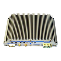
Controls system noise by selecting common or floating ground for input signal.
Sets amplifier to stereo (STR) or bridged (BRDG) mono operation for desired audio output.
Adjusts bass level and matches signal source output to amplifier input for optimal performance.
OVR LED signals overload; THL LED signals heatsink overheating for protection.
ON LED confirms amplifier is powered on with a stable 12V supply.
Ensure 2" clearance for heat dissipation; mount upright or horizontally, never upside down.
Check space for cables, ensure LED visibility, use template, drill pilot holes, and secure with screws.
Use largest gauge power/ground cables; MS275 accepts up to 7ga, MPS2240 up to 4ga.
Place fuse/breaker within 18" of battery, rated no more than 30 Amps per amplifier.
Guide to choosing correct power cable gauge based on power and cable run distance.
Use largest gauge speaker wire (up to 10ga) for best damping factor; ensure secure connections.
Run audio cables away from power wires to reduce noise; use high-quality shielded interconnects.
Understand Green (on), Yellow (thermal), Red (impedance/fault), and flashing patterns for system status.
| Brand | Phoenix Gold |
|---|---|
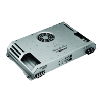
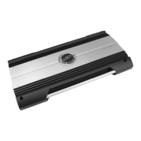
| Model | MS 275 |
| Category | Amplifier |
| Language | English |