SPECIFICATIONS
9300 North Decatur • Portland, OR 97203
Tel: 503.286.9300 • F ax: 503.978.3380
w w w .phoenixgold.com
• Variable 12dB per octave highpass crossover from 40 to 800Hz
• Variable 12dB or 24dB (Front Input Only) per octave lowpass crossover from 40 to 800Hz
• Adjustable 0 to +15dB Twin-T™ 45Hz bass boost
• Remote Monitoring Display output connects to optional RMD voltage display
• LPL Ready: optional LPL44 allows the subwoofer level to be adjusted from the dash
• TAIM™ Muting circuitry for soft turn-on and turn-off
• Fully complimentary output stages
• Advanced overload and thermal protection circuitry
• High current buss bars for all high current/high voltage stages
• PWM MOSFET power supply
• Gold plated high current power and speaker terminals
• Gold plated signal input jacks
• Unique black anodized heatsink with fly cut fins
• Optional QLink/2 available for seamless installation of multiple amplifiers
FEATURES
* For complete manuals, technical tips, FAQ’s, system diagrams and new product information visit us @
The QX Series Amplifiers are designed with an emphasis on exceptional power, superior sonic excellence, high performance features and
unmatched cosmetics.
Continuous Output Power at 1% THD (watts):
QX500.5
Front and Rear Channels:
Into 4 ohms @ 12.5(IASCA) /14.4 VDC . . . . . . . . . . . . . . . . . . . . . . . . . . . . . . . . . . . . . . . . . . . . . . . . . . . .37.5/50 x 4
Into 2 ohms @ 14.4 VDC . . . . . . . . . . . . . . . . . . . . . . . . . . . . . . . . . . . . . . . . . . . . . . . . . . . . . . . . . . . . . . . . . . .75 x 4
Bridged into 4 ohms @ 14.4 VDC . . . . . . . . . . . . . . . . . . . . . . . . . . . . . . . . . . . . . . . . . . . . . . . . . . . . . . . . . . . .150 x 2
Sub Channel:
Into 4 ohms @ 12.5(IASCA) /14.4 VDC . . . . . . . . . . . . . . . . . . . . . . . . . . . . . . . . . . . . . . . . . . . . . . . . . . . .150/175 x 1
Into 2 ohms @ 14.4 VDC . . . . . . . . . . . . . . . . . . . . . . . . . . . . . . . . . . . . . . . . . . . . . . . . . . . . . . . . . . . . . . . . . .225 x 1
Recommended Fuse Size . . . . . . . . . . . . . . . . . . . . . . . . . . . . . . . . . . . . . . . . . . . . . .2 x 20 amp and 1 x 40 amp ATO
Chassis Dimensions . . . . . . . . . . . . . . . . . . . . . . . . . . . . . . . . . . . . . . . . . . . . . . . . . . . . . . . . . . .19.75L x 9.5W x 2.1H
Overall Dimensions . . . . . . . . . . . . . . . . . . . . . . . . . . . . . . . . . . . . . . . . . . . . . . . . . . . . . . . . . . .20.75L x 9.5W x 2.1H
Total Harmonic Distortion . . . . . . . . . . . . . . . . . . . . . . . . . . . . . . . . . . . . . . . . . . . . . . . . . . . . . . . . . . . . . . . . . .<0.02%
Frequency Response . . . . . . . . . . . . . . . . . . . . . . . . . . . . . . . . . . . . . . . . . . . . . . . . . . . . . . . . . . .±1dB 20Hz to 20kHz
Signal to Noise Ratio (20Hz to 20kHz) . . . . . . . . . . . . . . . . . . . . . . . . . . . . . . . . . . . . . . . . . . . . . . . . . . . . . . . .>100dB
Signal Input Sensitivity . . . . . . . . . . . . . . . . . . . . . . . . . . . . . . . . . . . . . . . . . . . . . . . . . . . . . . . .200 millivolts to 4 volts
DC Input Voltage Range . . . . . . . . . . . . . . . . . . . . . . . . . . . . . . . . . . . . . . . . . . . . . . . . . . . . . . . . . .10 Vdc to 15.5 Vdc
Typical current draw at idle . . . . . . . . . . . . . . . . . . . . . . . . . . . . . . . . . . . . . . . . . . . . . . . . . . . . . . . . . . . . . .<1.5 amps
Bass Boost . . . . . . . . . . . . . . . . . . . . . . . . . . . . . . . . . . . . . . . . . . . . . . . . . . . . . . . . . . . . . . . . . . .0 to 15dB @ 45Hz
Highpass Crossover Slopes . . . . . . . . . . . . . . . . . . . . . . . . . . . . . . . . . . . . . . . . . . . . . . . . . . . . . . . . .12dB per Octave
Lowpass Crossover Slope . . . . . . . . . . . . . . . . . . . . . . . . . . . . . . . . . . . . . . . . . . . . . . . . . . . . .12 or 24dB per Octave
Crossover Range . . . . . . . . . . . . . . . . . . . . . . . . . . . . . . . . . . . . . . . . . . . . . . . . . . . . . . . . . . . . . . . . . . . .40 to 800Hz
Minimum Load Stability for all channels . . . . . . . . . . . . . . . . . . . . . . . . . . . . . . . . . . . . . . . . . . . . . . . . . . . . . . .2 ohms
Due to on-going continuous product development, features, specifications and availability are subject to change without notice.
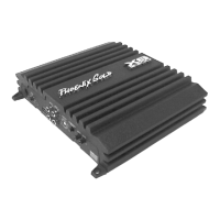
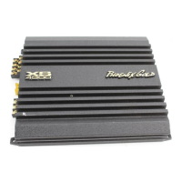
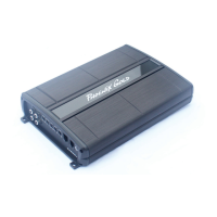
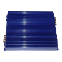
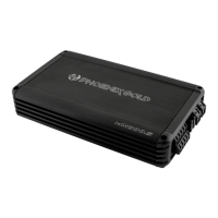
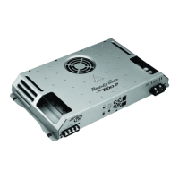
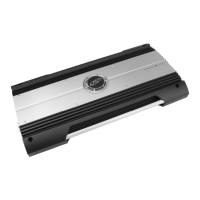
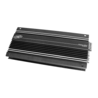
QX500.5 Five Channel Amplifier
QX500.5 Five Channel Amplifier
LIMITED WARRANTY
Phoenix Gold International, Inc. (or "Phoenix Gold") warrants its products against defects in materials and workmanship for a limited period of time.For a period of one (1) year from date of original purchase, we will
repair or replace the electronic product, at our option, without charge for parts and labor. Customer must pay all parts, labor and shipping charges after the limited warranty period expires. The
limited warranty period for factory refurbished products expires after ninety (90) days from date of original purchase. This limited warranty applies only to purchases from authorized
Phoenix Gold Electronics/Speaker retailers.
This limited warranty is extended only to the original purchaser and is valid only to consumers in the United States. Consumers are required to provide a copy of the original sales invoice from
an authorized Phoenix Gold dealer when making a claim against this limited warranty. This limited warranty only covers failures due to defects in materials or workmanship that occur during normal
use. It does not cover failures resulting from accident, misuse, abuse, neglect, mishandling, misapplication, alteration, faulty installation, modification, service by anyone other than Phoenix
Gold, or damage that is attributable to Acts of God. It does not cover costs of transportation to Phoenix Gold or damage in transit.
This warranty will become void if the serial number identification has been wholly or partially removed, altered or erased. Repair or replacement under the terms of this warranty does not
extend the terms of this warranty.Should a product prove to be defective in workmanship or material, the consumer's sole remedies will be repair or replacement as provided under the terms of this
warranty. Under no circumstances shall Phoenix Gold be liable for loss or damage, direct, consequential or incidental, arising out of the use of or inability to use the product. There are no
express warranties other than described above.