Amplifier Owner’s Manual
© 2019 Phoenix Gold • www.phoenixgold.com © 2019 Phoenix Gold • www.phoenixgold.com
Amplifier Owner’s Manual
MX 800.5
MULTI-CHANNEL POWER AMPLIFIERS
MX 800.5
MULTI-CHANNEL POWER AMPLIFIERS
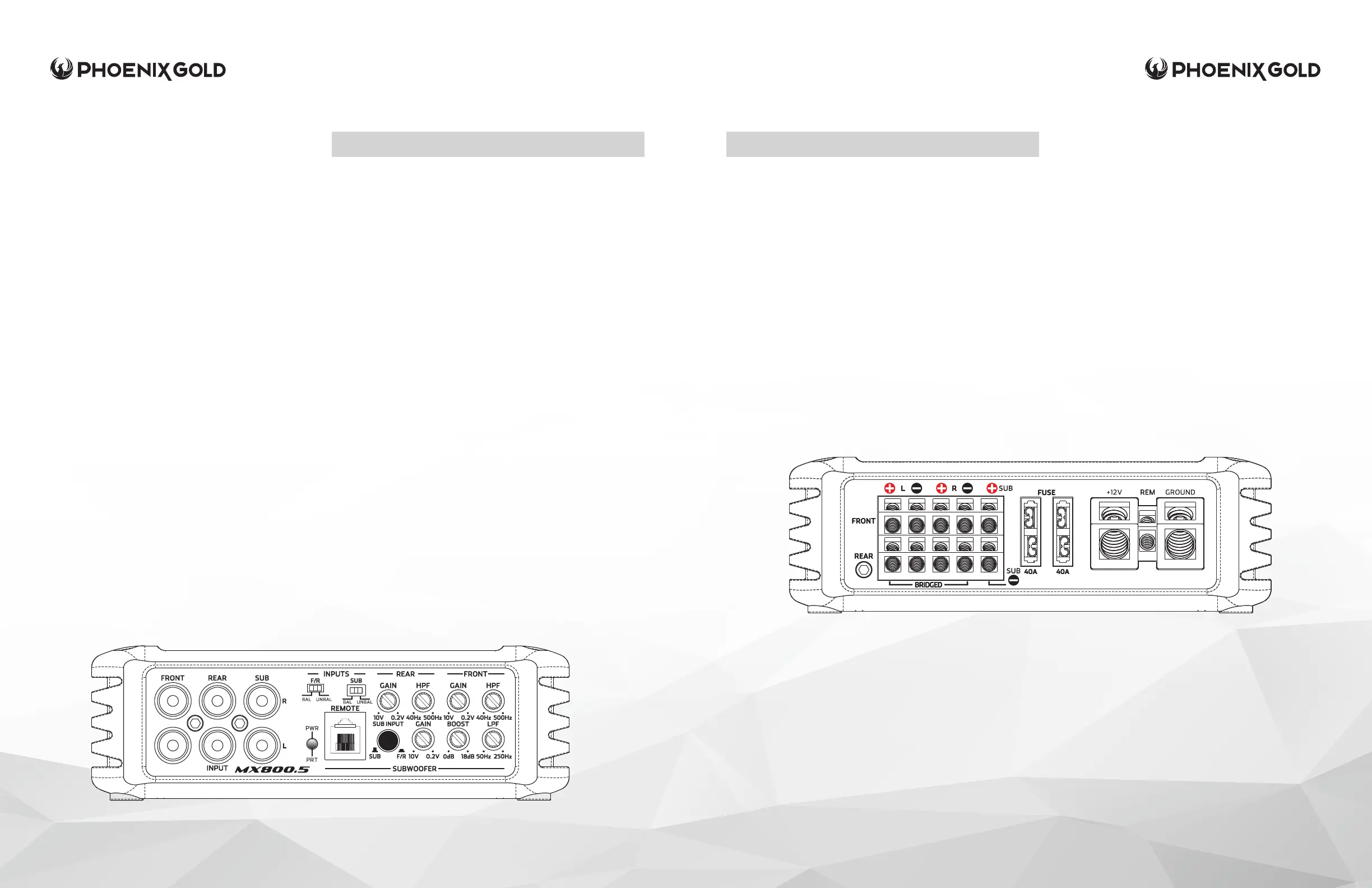
SPEAKER OUTPUTS
Used to connect the amplier to speakers.
The MX 800.5 minimum impedance is 2 Ohms
on channels 1-4 and 4 Ohms on SUB output. If
Front or Rear channels are bridged, minimum
impedance is 4 ohms on the bridged channels.
FUSE
On-Board fuse protection via ATC fuses. If blown,
only replace with same value fuses (2 x 40A)or
risk damage to unit and voiding the warranty.
+12V
This must be connected to the fused positive terminal
(+12V) of the car’s battery. A fuse must be located
within 18 inches of the battery to protect the vehicle
and should be fused at, or above, the ampliers fuse
rating.
REMOTE (REM)
This must be connected to switched +12V, usually a
trigger wire coming from the head unit or an ignition
lead if one is not available.
GROUND
This must be connected to the negative terminal of the
car’s battery or bolted to a clean, unpainted part of the
chassis of the vehicle, use of an Stinger Expert Ground
Terminal (SPTE) is recommended. Bad grounds account
for 90% of amplier issues, make sure you ground the
amplier correctly and securely.
Features listed below are in order from left to right
on the amplier.
FRONT, REAR AND SUB INPUTS
Connect preamp signal cables from head unit to
these inputs. For a high-level signal, you will need
RCA to Speaker Wire Adaptors (Stinger X12LINE or
similar).
INPUTS (FRONT/REAR/SUB)
If you are using RCA or high level signal from an
aftermarket head unit, select UNBAL. If you are
using high level from a OEM Factory source unit or
amplier select BAL.
POWER/PROTECT LED
Amplier status indicator. Blue indicates all
systems working and amplier is on. Red indicates
protection mode, from Thermal, Short Circuit or
Blown Fuse. (See Troubleshooting)
REMOTE LEVEL CONTROL
This port is for connecting the remote subwoofer
level control. This allows up to 20dB of volume
adjustment. This is not a bass boost, it controls the
level of the low pass signal.
GAIN (REAR)
Used to adjust the input sensitivity to match
the input level signal on the Rear channels.
Continuously variable from 0.2V to 10V. Adjust this
with the help of a DMM and a test signal or an
Oscilloscope. See System Tuning section for setup
instructions.
HPF (HIGH PASS FILTER - REAR)
Controls the highpass crossover point for the Rear
channels. Continuously variable from 40Hz to 500Hz.
GAIN (FRONT)
Used to adjust the input sensitivity to match the input level
signal on the Front channels. Continuously variable from
0.2V to 10V. Adjust this with the help of a DMM and a test
signal or an Oscilloscope. See System Tuning section for
setup instructions.
HPF (HIGH PASS FILTER - FRONT)
Controls the highpass crossover point for the Front
channels. Continuously variable from 40Hz to 500Hz.
SUB INPUT
OUT if using the dedicated SUB inputs. IN if using only the
front or rear inputs and the amplier will internally split the
signal and send to the SUB channel.
GAIN (SUB)
Used to adjust the input sensitivity to match the input level
signal on the Sub channel. Continuously variable from
0.2V to 10V. Adjust this with the help of a DMM and a test
signal or an Oscilloscope. See System Tuning section for
setup instructions.
BOOST
Controls the bass boost from 0 to +18dB .
LPF (LOW PASS FILTER - SUB)
Controls the lowpass crossover point for the Sub channel.
Continuously variable from 50Hz to 250Hz.
 Loading...