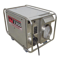
5 Service
CAUTION: Servicing the Phoenix D385 with its high voltage
circuitry presents a health hazard which could result in
death, serious bodily injury, and/or property damage. Only
qualified service people should service this unit.
CAUTION-ELECTRICAL SHOCK HAZARD: Electrical power
must be present to perform some tests; these tests should
be performed only by a qualified service person.
Note: Check for airflow at all inlets and outlets. Do not run
unit if no airflow is detected.
5.1 Warranty
A warranty certicate has been enclosed with this unit;
read it before any repair is initiated. If a warranty repair is
required, call the factory rst at 1-800-533-7533 for warranty
claim authorization and technical assistance.
5.2 Technical Description
The D385 produces airow using two permanent split
capacitor (PSC) blower motors. A shaded-pole gear motor
rotates the desiccant rotor via a pulley and belt. Heat for
reactivation is generated by a two-stage nichrome heating
element powered by two separate branch circuits. The
heating elements cannot be energized individually – both
cords must be plugged in for them to operate. An LED
indicator lamp illuminates when the unit is powered on. An
hour meter also counts the cumulative hours the unit has
run.
The blowers, rotor motor, heating elements, indicator lamp,
and hour meter are operated by a line-voltage control circuit.
One branch circuit (Circuit 1) delivers power to the process
blower, indicator lamp, hour meter, and a 1270W heating
element through one relay (Relay 1). A separate branch
circuit (Circuit 2) delivers power to the reactivation blower,
rotor motor, and a 1360W heating element through a second
relay (Relay 2). Circuit 1 provides power to the coil for Relay
2 and Circuit 2 provides power to the Relay 1 coil. Because
of this latching between the two circuits, the unit cannot
operate unless both cords are plugged in. With both cords
plugged in, turning on the power switch energizes the Relay
2 coil. This energizes all of the loads on Circuit 2, as well as
the Relay 1 coil, which energizes all of the loads on Circuit 1.
If either cord is unplugged, all loads are de-energized.
Three thermal cutout switches allow for safe operation of
the D385. Two of these cutouts are located in the heater. If
the reactivation inlet temperature is too high or if there is
insufcient reactivation airow, the automatically-resetting
heater cutout opens and all loads are de-energized. Once
the temperature drops by a few degrees F, the switch
closes again and the loads are re-energized. The second
5
www.UsePhoenix.com • sales@UsePhoenix.comToll-Free 1-800-533-7533
Reactivation air stream lter:
This 12”x12 x1” lter is located in the bottom of your D385.
To change the reactivation air lter, lay the D385 down in a
horizontal position. The lter access slot is located on the
bottom of the machine (Fig. 4). Open retainment clip, remove
old lter, and replace with fresh lter.
The stock lter supplied carries a MERV-7 ltration efciency
rating. This ltration prevents plugging the heater or loading
the desiccant wheel with foreign matter.
Operating the unit with a dirty lter will reduce the
dehumidier’s capacity and efciency and may cause the
heater coil to cut out on thermal overload.
The lter can generally be vacuumed clean several times
before needing replacement. Replacement lters can be
ordered from the factory or purchased locally if available.
DO NOT operate the unit without the lters or with less
effective lters as the desiccant wheel inside the unit will
become clogged and require disassembly to clean.
4.2 Blower Motors and Rotor Drive Motor
All motors on the D385 are permanently lubricated and do
not require maintenance.
4.3 Desiccant Rotor Cassette Assembly
The cassette can be easily removed to inspect and/or clean
the seals and rotor. Reverse these steps to reinstall the
cassette.
PROCESS BLOWER
GRN 25
BLK 11
WHT 24
CORD 1 CORD 2
WHT WHTBLK
BLK
BLK
BRN
BLU 27
BLU
BLU
RED
RED
WHT 9
BLK 8
BLU 7
ORG 6
BLU
BLK
GRN
BLK
BLK
BLK
TERMINAL BLOCK
TERMINAL BLOCK
CIRCUIT 1 CIRCUIT 2
HEATER
THERM OL 1
176°F
HEATER
THERM OL 2
302°F
1360W
1270W
ROTOR MOTOR
1234
1234
REGEN CAPACITOR
REGEN BLOWER
PROC THERM
OL 140°F
MAIN POWER SWITCH
HOUR METER
PROC BLOWER PROC CAP
LIGHT
RELAY 1 RELAY 2
BLU 22
ORG 15
ORG 18
ORG 19BLU 21
BLU 20
ORG 6
ORG 15
ORG 12
ORG 28
BLK 1
ORG 14
BLK 17
BLK 11
BLK 10
BLK 10
BLU 27
WHT 4
BLK 8
BRN 5
BLK 3BLK
BLU
BRN
ORG 28
ORG 14
BLK 2
BLK 1
BLU 26
WHT 13
WHT 13
BLU 7
WHT 23
WHT 24
BLU 22
BLU 26
WHT 9
WHT 4
BLU 23
BLK 16BLK 3
BRN 5
BLK 2
WHT 23
1
2
3
4
LINE LINE
ROCKER
SWITCH POLE 1
ROCKER
SWITCH
POLE 2
NEUTRAL NEUTRAL
RELAY
CONTACT 1
1270W HEATER
1360W HEATER
HOUR METER
LAMP
HEATER
CUTOUT 1
RELAY COIL 2
PROCESS
CAPACITOR
HEATER
CUTOUT 2
PROCESS
CUTOUT
RELAY
CONTACT 2
REIGN
CAPACITOR
RELAY COIL 1
ROTOR MOTOR
REIGN BLOWER
BLU
BLK
BRN
BLU
BLK
BRN
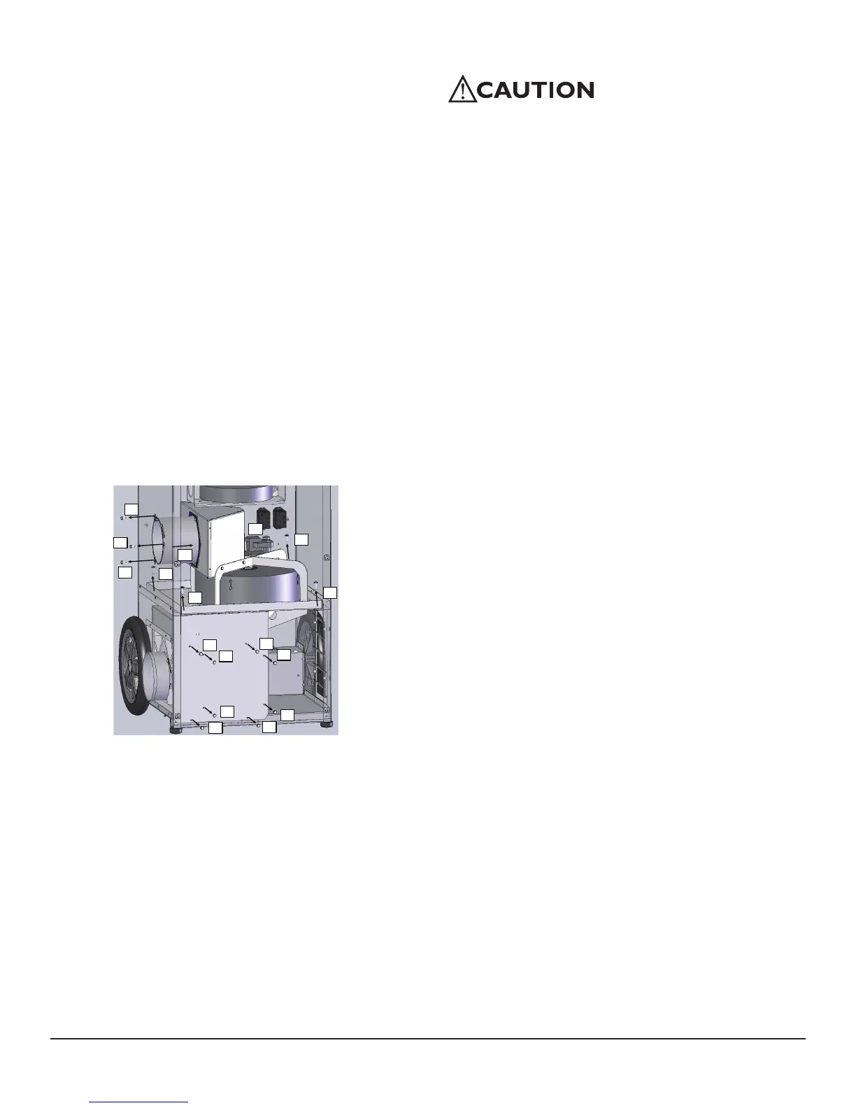
Step 1: Remove three #10 screws holding reactivation duct in place
(1A, 1B, 1C) using 5/16” hex driver.
Push duct section (1D) in toward wheel
Step 2: Unplug wheel drive motor wires (2)
Step 3: Remove four ¼” screws holding cassette in place
(3A-3D) using #3 Phillips driver
Step 4: Remove eight #10 screws holding reactivation inlet cover in place
(4A-4H) using 5/16” hex driver. Remove reactivation inlet panel
Step 5: Lift cassette up and out of cabinet to avoid tearing
lower reactivation gasket
Step 6: Installation is reverse of removal
Cassette Removal Instructions