Evaporator coil frosted continuously, low dehumidifying
capacity.
1. Defrost thermistor loose or defective
2. Low refrigerant charge
3. Dirty air lter or restricted air ow
4. Upper housing is not sealed to lower housing
Compressor runs with POWER button OFF.
1. Defective relay
2. Defective control board
3. Upper housing not sealed to tower
5.3 Air Mover
The motorized impeller has a PSC motor and internal thermal
overload protection. If defective, the complete assembly must
be replaced.
1. Unplug power cord
2. Remove the four screws attaching the bottom plate to
the lower housing
3. Disconnect the impeller leads
4. Remove the four screws holding the impeller to the
bottom plate
5. Reassemble the new impeller using the above procedure
in reverse
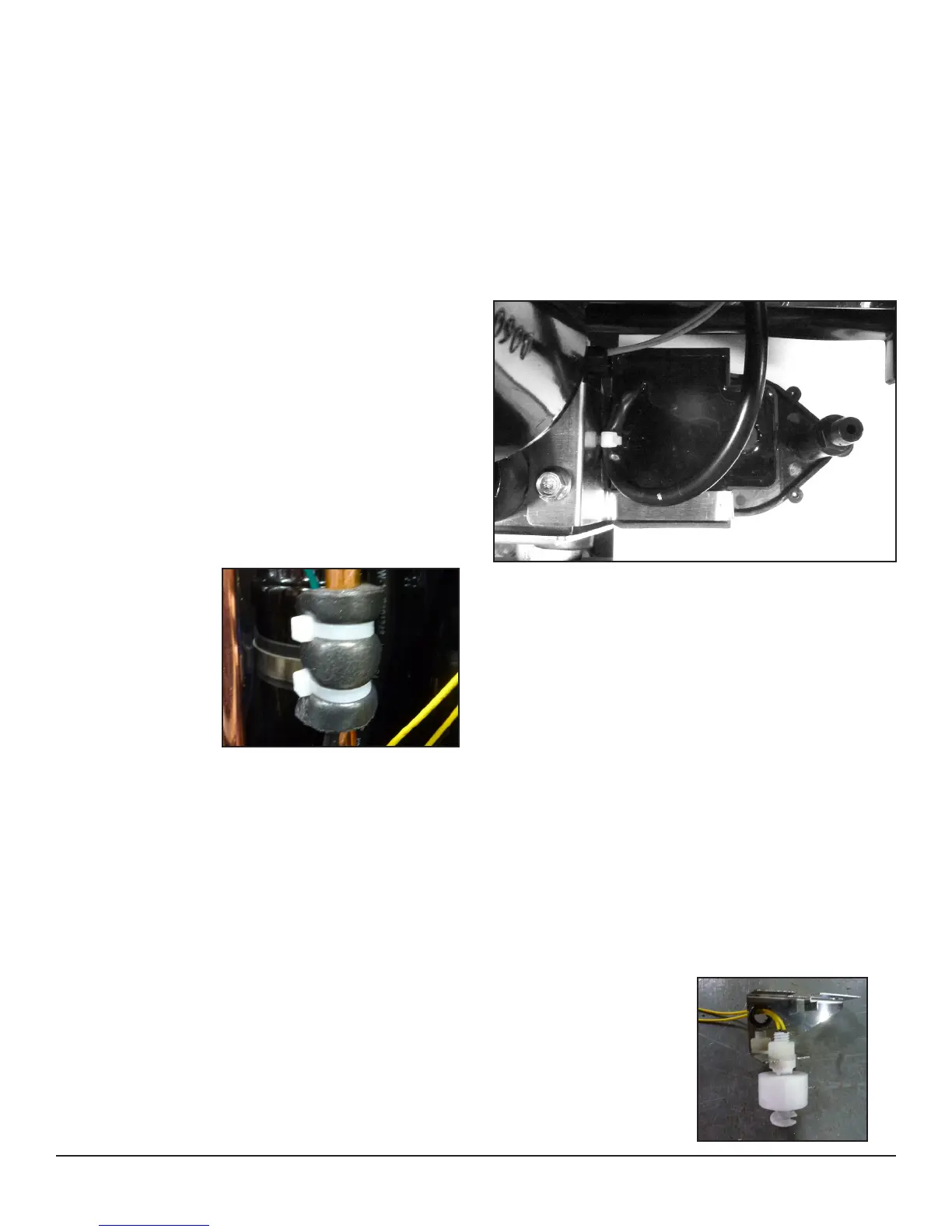
5.4 Thermistor
The defrost thermistor
is attached to the
refrigerant suction
line between the
accumulator and the
evaporator.
To replace thermistor:
1. Unplug the
dehumidier
2. Remove the front housing
3. Cut cable ties and remove insulation and aluminum tape.
4. Remove control panel
5. Unthread thermistor from control housing grommet
6. Detach thermistor from control board jumper
7. Reassemble thermistor and dehumidier using the above
procedure in reverse
Figure 10: Picture of
the oat safety switch.
5.5 Condensate Pump
The internal condensate pump removes water that collects in
the reservoir.
To replace the condensate pump:
1. Unplug the unit
2. Remove the front housing
3. Unplug the pump wires from the wire harness
4. Remove the condensate hose and the one screw
attaching the pump bracket to the compressor support
5. Replace the pump, hose, wiring, bolts, and housing in
the reverse order
5.6 Float Safety Switch
The oat safety switch activates when the water rises too
high in the condensate reservoir. The oat safety switch
turns off the compressor until the water level lowers and
disengages the switch.
To replace the oat safety switch
1. Unplug the dehumidier
2. Remove the front housing
3. Unplug the oat safety switch wires from the wire
harness
4. Remove the one screw attaching the pump and oat
switch bracket to the compressor support
5. Remove the pump from the reservoir and slide out the
oat switch from under the compressor support
6. Replace the oat, pump, wiring, bolts and housing in the
reverse order
6
www.UsePhoenix.com • sales@UsePhoenix.comToll-Free 1-800-533-7533
Figure 9: Picture of pump and oat switch brackets screw.
Figure 8: Thermistor attached to the
refrigerant line.
 Loading...