MICRO VI USER’ S MANUAL Page 5PHONIC CORPORATE
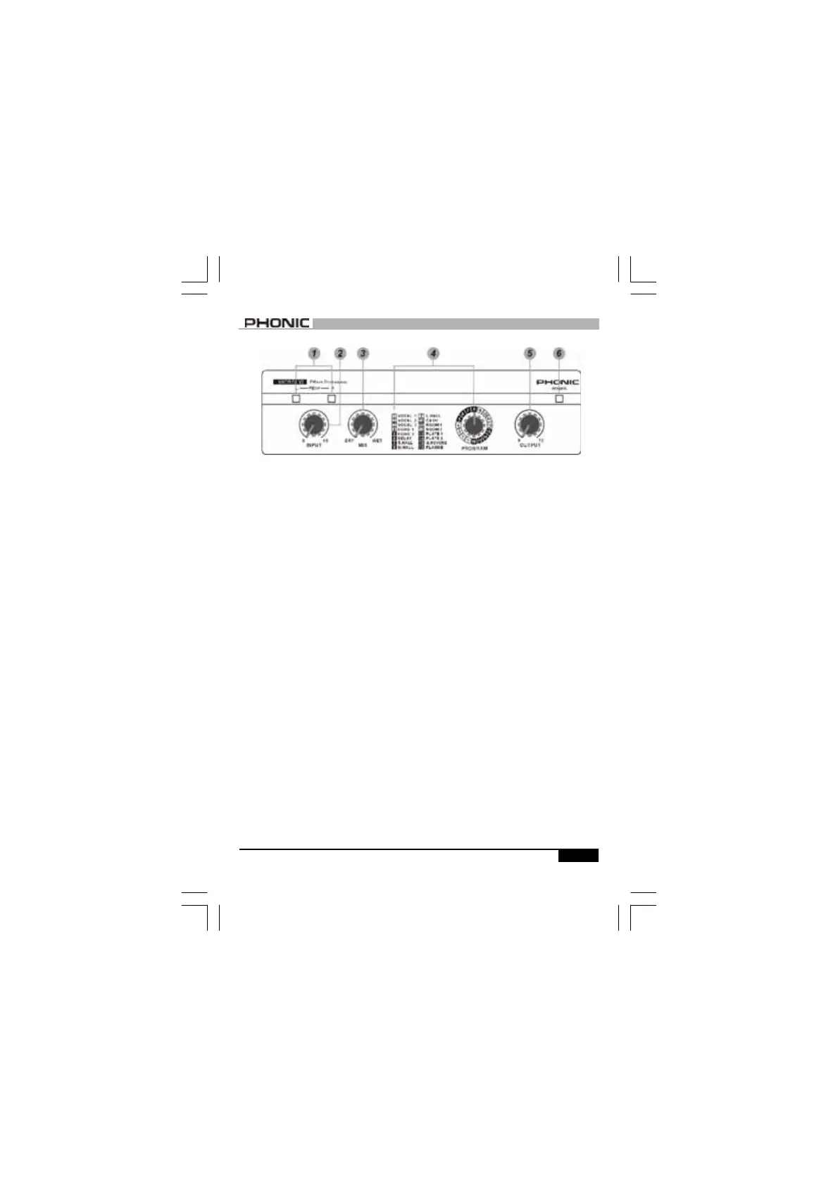
FRONT PANEL
FRONT PANEL
1. SIGNAL/PEAK (L/R) INDICATOR
There is one bi-color LED for left and
right channel respectively. In most
cases, they light up green as signal
LEDs, and turn red when receiving a
peak level signal. In general, a few
red flashes every now and then will
not be a problem. If one of the LEDs
flash red very often or remains on,
the input level should be reduced.
2. INPUT LEVEL CONTROL
The input control knob sets the level
going into MICRO VI. The level should
be set so that Peak indicators flash
red only occasionally.
3. MIX (DRY / WET) CONTROL
This control sets the balance between
the unaffected signal coming through
the inputs and the effect-processed
signal being generated by MICRO
VI(i.e.: the balance of wet
and
dry/
e
ffect
-
processed and
w
ith no ef-
fect). By keeping it somewhere in the
center, a blend of dry and wet signal
can therefore be produced.
4. PROGRAM
The list on the left shows you the 16
effect programs available on MICRO
VI. Use the detented control knob to
select one of the 16 effects for the
main output.
5. OUTPUT CONTROL
This rotary control knob sets the sig-
nal level going to the amplifier or
mixer from the output of MICRO VI.
6. POWER INDICATOR
This red LED will illuminate when
adapter is plugged in.