MICRO VI USER’ S MANUAL PHONIC CORPORATEPage 6
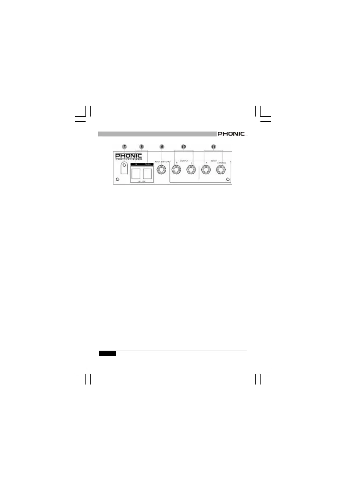
BACK PANEL
BACK PANEL
7. CORD CINCH
After connect the power cord to the
AC input, use a screwdriver to
unscrew it and place the power cord
inside of the cinch to safely secure
the power cable.
8. POWER SUPPLY INPUT SOCKET
Connect the power cable in the IN
socket. You may use another power
cable to connect one MICRO VI to
another by connecting the THRU to
IN.
9. FOOTSWITCH
A 1/4
”
mono phone jack for connect-
ing a momentary foot switch; users
can easily activate/cancel the effect
program via the foot switch.
10. OUTPUT (LEFT & RIGHT)
They are two 1/4
”
mono jacks for
connection such as effects returns
on a mixing console.
11. INPUT (LEFT/MONO & RIGHT)
A pair of 1/4
”
mono jacks for user
to connect to sources such as
effects sends of a mixing console.
For mono applications, use only the
“
L(MONO)
”
input.