Do you have a question about the Phonic Powerprod 740 and is the answer not in the manual?
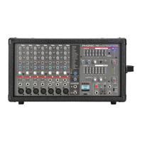
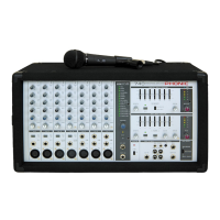
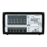
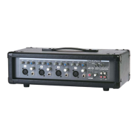
Illustrates the front and rear panel controls, connectors, and indicators of the mixer.
Visual representation of the mixer's internal signal path and functional blocks.
Schematic and layout diagram for the mixer's input channel printed circuit board.
Schematic and layout diagram for the mixer's master control and output printed circuit board.
Schematic and layout diagram for the digital effects processing printed circuit board.
Schematic and layout diagram for the mixer's power amplifier printed circuit board.
Schematic and layout diagram for the mixer's output and power switch circuitry.
Detailed schematic for input/output circuitry of channels 1 and 2.
Detailed schematic for input/output circuitry of channels 3 and 4.
Detailed schematic for input/output circuitry of channels 5 through 8.
Schematic for auxiliary and tape input/output connections and processing.
First part of schematics for main summing, equalization, and display functions.
Second part of schematics for main summing, equalization, and display functions.
Schematic detailing the digital effects processing circuitry.
Schematic for reverb's analog-to-digital and digital-to-analog converters.
Schematic for the reverb's digital signal processing unit.
Schematic for the reverb effect's control circuitry.
Schematic for the left channel power amplifier circuit.
Schematic for the right channel power amplifier circuit.
Schematics for the output stage relays and speaker connections.
Schematic detailing the mixer's internal power supply unit.
List of components and their specifications for the channel printed circuit board.
List of components and their specifications for the power amplifier PCB.
List of components and their specifications for the master control PCB.
List of components and their specifications for the digital effect PCB.
List of various non-component items, accessories, and hardware.
Information on power specifications, voltage, and certifications for different regions.
Physical measurements of the mixer unit in millimeters and inches.
| EQ Bands | 3-band |
|---|---|
| Phantom Power | Yes |
| EQ | 3-band |
| Effects | No |
| Type | Analog |
| Aux Sends | 1 |
| Inputs | 2 x XLR, 2 x RCA |
| Outputs | 2 x XLR, 2 x RCA |