10
EN
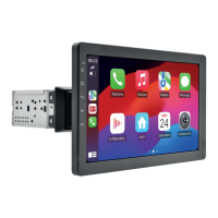
Connections
2
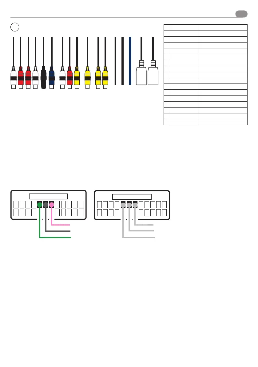
CABLING IN/OUT
A
RL OUT White - Rear Left
B
RR OUT Red - Rear Right
C
FL OUT Red - Front Right
D
FR OUT White - Front Left
E
MICROFONO
F
SUB OUT Blue - Sub Woofer Output
G
AUX - R AUDIO White - Right Audio Input
H
AUX - L AUDIO Rosso - Left Audio Input
I
AUX - VIDEO Yellow - Video Input
J
CAM-IN Yellow - Camera Input
K
VIDEO OUT 1 Yellow - Video 1 Output
L
VIDEO OUT 2 Yellow - Video 2 Output
M
IR SENSOR IR Sensor - NOT ENABLED
N
GROUD GND GND Ground
O
+12 V
P
USB 1 MULTIFUNCTION
Q
USB 2 MULTIFUNCTION
A B C D E F G H I M N O P QJ K L
USB
USB
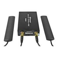
Resistive steering wheel control
Please follow the diagrams reported in the user manual of interface 04083 on www.phonocar.com , to connect the device to the
original car connector.
To download it, please type the code of the interface in the “quick search” field on the Home Page. Scroll to the bottom of the
page, and click “Download”.
For cars with CAN line it is necessary to connect the CAN-BUS steering wheel control interface.
CONNECTION EXAMPLE
PINK
GREY
GREEN
SWC1
SWC2
GND