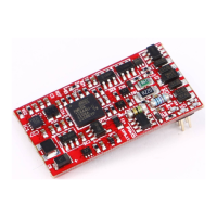
3.3 Settings and Special Functions
You can assign individual addresses to the switch decoder (e.g. address 18). You
can also set individual decoder switching times for both switching directions (e.g.
signals etc.). The switching time can be set in 15 steps at intervals of 0.25 s. The
decoder can also be programmed for continuous operation (e.g. to switch the
lighting) or for automatic switch-back. In this case, light cars will not experience any
problems when forcing open the switch points, as the switch point will switch over
after an adjustable delay time.
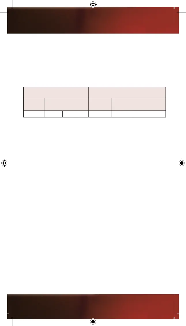
FACTORY SETTINGS EXAMPLE FOR INDIVIDUAL SETTINGS
Address
power duration in sec.
left right
Address
power duration in sec.
left right
1 0,75 0,75 18 0,75 0,25
See chapter 4 “Programming, Read-out and Setting” for further information.
You can also program the decoder for continuous operation. This can be used
to switch light signals (red/green). Both switching directions of the output can be
programmed separately. See the CV list in chapter 5 for instructions on this.
4. Programming, Read-out and Settings
Your switch decoder is pre-set to address 1. You can re-program your switch
decoder, e.g. if you want to change settings or assign different addresses. If you are
expanding your system in order to control additional switches or devices, you need
to program each additional switch decoder accordingly (addresses, special functions
etc.).
The programming is done via so-called CVs (Conguration Variables). Each CV
has a particular task or function which you can assign or set by specifying the
corresponding values.
Examples:
CV32 = address; CV51 / CV52 / CV75 = special functions. The CV table shows you
all possible CVs which you can edit. See chapter 5.
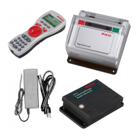
4.1 Connection for Programming
For programming, the decoder must be connected to the programming track output
of the digital central station via the screw terminals. (For the PIKO central station
35010, the digital track is also used for programming). A switch machine should be
connected to the output of the decoder (two pins). This way, the decoder can send a
return signal to the central station or the handheld control unit during programming or
read-out. The programming is done via so-called CVs (Conguration Variables). See
chapter 5.0 for all programmable CVs.
Caution: When programming on the main layout track, remove any
locomotives from the track: Otherwise, their programming could be affected.
18
 Loading...