EasyManua.ls Logo

Pioneer A-07 User Manual

Pioneer A-07
20 pages
To Next Page IconTo Next Page
Page #1 background imageLoading...
Page #1 background image
Service
Manual
STEREO
AMPLIFIER
A-07
ORDER
NO.
ARP2895
THIS
MANUAL
IS
APPLICABLE
TO
THE
FOLLOWING
MODEL(S)
AND
TYPE(S).
|_
Model
Power
Requirement
A-07
ee
oe
CONTENTS
1.
EXPLODED
VIEWS,
PACKING
AND
PARTS
LIST
o...cccsciscssissssecccccsvcocvcsesasccoecussecscacneacte
2
2.
SCHEMATIC
AND
PCB
CONNECTION
DIAGRAMG
..............:ccccsssscsssssssccsessseesecenescseensecsees
8
3.
PCB
PARTS
LIST
.................cescssssesecetessnnssesesenees
19
4.
BLOCK
DIAGRAM
...................:::cccsessssnscreseersenee
23
5.
ADJUSTMENTS
...............cccccessssserssececeesssssnsenees
24
6.
PANEL
FACILITIES
....................:-s:ssssesssessesneeeees
25
7.
SPECIFICATIONS
...................scsesscsseceescessesneeteeee
26
PIONEER
ELECTRONIC
CORPORATION
4-1,
Meguro
1-Chome,
Meguro-ku,
Tokyo
153,
Japan
PIONEER
ELECTRONICS
SERVICE
INC.
PO
Box
1760,
Long
Beach,
CA
90801-1760,
U.S.A.
PIONEER
ELECTRONIC
[EUROPE]
N.V.
Haven
1087,
Keetberglaan
1,
9120
Melsele,
Belgium
PIONEER
ELECTRONICS
ASIACENTRE
PTE.
LTD.
501
Orchard
Road,
#10-00
Lane
Crawford
Place,
Singapore
0923
©
PIONEER
ELECTRONIC
CORPORATION
1995
O-FFC
MAY.
1995
Printed
inJapan
Question and Answer IconNeed help?

Do you have a question about the Pioneer A-07 and is the answer not in the manual?

Pioneer A-07 Specifications

General IconGeneral
BrandPioneer
ModelA-07
CategoryAmplifier
LanguageEnglish

Summary

Exploded Views, Packing, and Parts List

Detailed Parts List

Detailed list of components with part numbers for the A-07 stereo amplifier.

Product Packing Details

Describes the packaging components and procedure for the A-07 amplifier.

Schematic and PCB Connection Diagrams

Wiring and PCB Connection Diagrams

Comprehensive wiring and PCB connection diagrams for various amplifier assemblies.

PCB Parts List

Assembly Parts Lists Overview

Detailed parts lists for various assemblies including M-CON, AF, LED, and Motor Vol ASSYs.

Miscellaneous PCB Components

Miscellaneous parts and components listed under the PCB parts section.

Block Diagram

Adjustment Procedures

Technical Specifications

Panel Facilities Overview

Front Panel Controls and Indicators

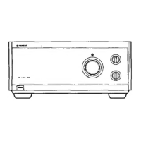
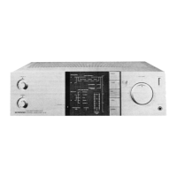
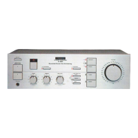
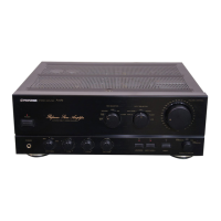
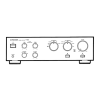
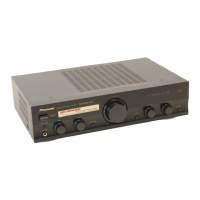
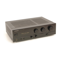
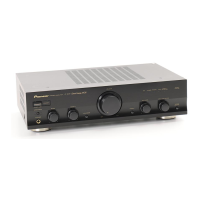
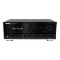
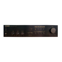
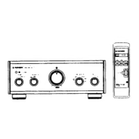
Description of controls and indicators on the front of the amplifier.

Rear Panel Connectors and Terminals

Description of connectors and terminals on the rear of the amplifier.

Related product manuals