EasyManua.ls Logo

Pioneer A-447 User Manual

Pioneer A-447
19 pages
To Next Page IconTo Next Page
Page #1 background imageLoading...
Page #1 background image
RPIONGER’
_
The
future
of
sound
and
vision.
-44/
6
a
STEREO
AMPLIFIER
AMPLIFICATEUR
STEREO
MPIONEER
arenao
anmvone
Operating
Instructions
Mode
d’emploi
The
illustration
shows
model
A-447.
L’illustration
motre
le
modéle
A-447.
WARNING:
To
preEveENT
FIRE
OR
SHOCK
HAZARD,
DO
NOT
EXPOSE
THIS
APPLIANCE
TO
RAIN
OR
MOISTURE.
IMPORTANT
NOTICE
[For
U.S.
and
Canadian
models]
The
serial
number
for
this
equipment
is
located
on
the
rear
panel.
Please
write
this
serial
number
on
your
enclosed
warranty
card
and
keep
it
in
a
secure
area.
This
is
four
your
security.
[For
Canadian
model]
CAUTION:
to
prevent
ELECTRIC
SHOCK
DO
NOT
USE
THIS
(POLARIZED)
PLUG
WITH
AN
EXTENSION
CORD,
RECEPTACLE
OR
OTHER
OUTLET
UNLESS
THE
BLADES
CAN
BE
FULLY
INSERTED
TO
PREVENT
BLADE
EXPOSURE.
ATTENTION:
pour
prevenir
LES
CHOCS
ELECTRIQUES
NE
PAS
UTILISER
CETTE
FICHE
POLARISEE
AVEC
UN
PROLONGATEUR
UNE
PRISE
DE
COURANT
OU
UNE
AUTRE
SORTIE
DE
COURANT,
SAUF
SI
LES
LAMES
PEUVENT
ETRE
INSEREES
A
FOND
SANS
EN
LAISSER
AUCUNE
PARTIE
A
DECOUVERT.
IMPORTANT
LINE
VOLTAGE
SELECTOR
SWITCH
Only
multi-voltage
models
are
provided
with
these
switches.
U.S.
and
Canadian
models-are
not
provided
with
the
switches.
Mains
voltages
in
Saudi
Arabia
are
127V
and
220V
orily.
Never
use
this
model
with
110V
setting
in
Saudi
Arabia.
The
line
voltage
selector
switches
are
on
the
rear
panel.
Before
your
model
is
shipped
from
the
factory,
these
switches
are
set
to
the
power
requirements
of
the
destination.
Check
that
they
are
set
properly
before
plugging
the
power
cord
into
the
AC
outlet.
If
the
voltages
are
not
|
properly
set
or
if
you
move
to
an
area
where
the
voltage
requirements
differ,
adjust
the
selector
switches
as
follows.
1.
Use
a
medium-size
screwdriver.
2.
Insert
the
screwdriver
in
the
groove
to
the
voltage
selector,
and
adjust
so
that
the
tip
of
the
groove
points
to
the
voltage
value
of
a
VOLTAGE
SELECTOR
10-127V
TOV
240v
720
Medium-size
screwdriver
i=
The
lightning
flash
with
arrowhead,
within
an
equilateral
triangle,
is
intended
to
alert
the
user
of
the
presence
of
uninsulated
“dangerous
voltage”
within
the
product's
enclosure
that
may
be
of
sufficient
magni-
tude
to
constitute
a
risk
of
electric
shock
to
persons.
CAUTION
RISK
OF
ELECTRIC
SHOCK
DO
NOT
OPEN
CAUTION:
TO
PREVENT
THE
RISK
OF
ELECTRIC
SHOCK,
DO
NOT
REMOVE
COVER
(OR
BACK).
NO
USER-SERVICEABLE
PARTS
INSIDE.
REFER
SERVICING
TO
QUALIFIED
SERVICE
PERSONNEL.
The
exclamation
point
within
an
equilateral
triangle
is
intended
to
alert
the
user
of
the
presence
of
important
operating
and
maintenance
(servicing)
instructions
in
the
literature
accompanying
the
appliance.
Question and Answer IconNeed help?

Do you have a question about the Pioneer A-447 and is the answer not in the manual?

Pioneer A-447 Specifications

General IconGeneral
BrandPioneer
ModelA-447
CategoryAmplifier
LanguageEnglish

Summary

Important Notice

For U.S. and Canadian Models

Serial number location on rear panel for security and warranty card.

For Canadian Model

Caution to prevent electric shock with polarized plug and extension cords.

Line Voltage Selector Switch

Voltage Selector Adjustment

Instructions on how to adjust the voltage selector using a screwdriver.

Safety Instructions

General Safety Precautions

Guidelines on water, location, ventilation, heat, power sources, cord protection, polarization, and cleaning.

Appliance Handling and Servicing

Instructions for power lines, object/liquid entry, damage, and servicing.

Outdoor Antenna Grounding

Requirements for grounding outdoor antenna systems for surge protection.

Location

Installation Environment

Install in a well-ventilated area, avoiding high temperature, humidity, direct sun, or dust.

Features

Panel Facilities - Front Panel

Power Switch/Indicator

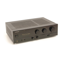
Button to turn the unit ON/OFF; indicator lights when power is on.

Speakers A Selector Switch

Switch to listen to speaker systems connected to SPEAKERS A terminals.

Panel Facilities - Front Panel Controls

Speakers B Selector Switch

Switch to listen to speaker systems connected to SPEAKERS B terminals.

REC Selector Switch

Selects recording source from TUNER, CD, TAPE, or SOURCE.

Input Selector Switch

Selects the playback source from LINE, TUNER, PHONO, or CD.

Volume Control

Adjusts playback volume and functions as a balance control.

Phono Selector Switch

Selects MM or MC cartridge type for turntable playback (A-447 only).

Muting Switch

Temporarily cuts sound volume; indicator lights when active (A-447 only).

Direct Switch/Indicator

Bypasses tone controls for flat, pure sound reproduction.

Loudness Switch/Indicator

Boosts low/high frequencies at low volumes (A-447 only).

Subsonic Filter Switch

Cuts super-low frequencies from records (A-447 only).

Panel Facilities - Tone Controls and Jacks

Treble Tone Control

Adjusts high-frequency tone; center is flat position.

Bass Tone Control

Adjusts low-frequency tone; center is flat position.

Phones Jack

For connecting headphones.

Panel Facilities - Rear Panel Connections

Phono Terminals

Connect turntable.

Adaptor Terminals

Connect adaptor components like graphic equalizers.

Line Terminals

Connect line-level audio sources.

DAT/Tape 1 Terminals

Connect DAT or Cassette decks for recording/playback.

Speakers B Terminals

Connect speaker system B (left and right channels).

Speakers A Terminals

Connect speaker system A (left and right channels).

Tape 2 Terminals

Connect Cassette deck for Tape 2 recording/playback.

CD Terminals

Connect CD player.

Tuner Terminals

Connect AM/FM tuner.

Turntable Ground Terminal

Connect turntable ground wire.

AC Outlets

Switched and unswitched outlets for connecting other equipment.

Voltage Selector

Multi-voltage selector switch for different power requirements.

Connections

Connecting Speaker Cords

Instructions for stripping wires, inserting, and tightening speaker terminals.

Speaker Impedance

Recommended speaker impedance for A/B terminals.

Connecting Input/Output Cords

How to connect RCA cables to input/output jacks.

Using Adaptor Terminals

Procedure for connecting components to adaptor terminals, including shorting bars.

AC Outlets (Switched)

Information on switched AC outlets for connected equipment.

AC Outlet (Unswitched)

Information on unswitched AC outlets for connected equipment.

Operations

Before Beginning Operations

Initial setup of controls and switches before operating the unit.

Playback Procedures

Steps for selecting playback source and adjusting volume.

Recording Tapes

How to select recording equipment and begin recording.

Monitor While Operating

Checking sound quality and recording level during tape recording.

Copying Tapes

Instructions for copying sounds from one cassette deck to another.

Playback Using a Graphic Equalizer

Adjusting sound with a graphic equalizer connected to adaptor terminals.

Troubleshooting

Troubleshooting Guide

Lists common symptoms, causes, and remedies for malfunctions.

Power-Cord Caution

Safety warnings and recommendations for handling the power cord.

Maintenance of External Surfaces

Guidelines for cleaning the unit's exterior surfaces.

Specifications

Amplifier Section - A-447

Technical specifications for the A-447 amplifier, including power output and frequency response.

Amplifier Section - A-337

Technical specifications for the A-337 amplifier, including power output and frequency response.

Power Supply/Miscellaneous

Details on power requirements, AC outlets, dimensions, and weight.

Related product manuals