EasyManua.ls Logo

Pioneer A-407R Service Manual

Pioneer A-407R
29 pages
To Next Page IconTo Next Page
Page #1 background imageLoading...
Page #1 background image
1. SAFETY INFORMATION ...................................... 2
2. EXPLODED VIEWS AND PARTS LIST ................ 3
3. SCHEMATIC DIAGRAM ....................................... 6
4. PCB CONNECTION DIAGRAM .......................... 14
5. PCB PARTS LIST ............................................... 19
6. ADJUSTMENT .................................................... 22
CONTENTS
7. GENERAL INFORMATION ................................ 23
7.1 IC INFORMATION ....................................... 23
7.2 BLOCK DIAGRAM....................................... 24
8. PANEL FACILITIES AND SPECIFICATIONS .... 25
A-407R
STEREO AMPLIFIER
ORDER NO.
RRV1958
T - IZK MAY 1998 Printed in Japan
PIONEER ELECTRONIC CORPORATION 4-1, Meguro 1-Chome, Meguro-ku, Tokyo 153-8654, Japan
PIONEER ELECTRONICS SERVICE, INC. P.O. Box 1760, Long Beach, CA 90801-1760, U.S.A.
PIONEER ELECTRONIC (EUROPE) N.V. Haven 1087, Keetberglaan 1, 9120 Melsele, Belgium
PIONEER ELECTRONICS ASIACENTRE PTE. LTD. 501 Orchard Road, #10-00 Wheelock Place, Singapore 238880
PIONEER ELECTRONIC CORPORATION 1998
c
THIS MANUAL IS APPLICABLE TO THE FOLLOWING MODEL(S) AND TYPE(S).
Type
Model
Power Requirement Remarks
A-407R
MY/EW AC220 – 230V
MY/GR AC220 – 230V
MV AC220 – 230V
STEREO AMPLIFIER
A-4 07R Direct Energy MOS
STANDBY/ON
STANDBY
OFF ON
POWER
A SPEAKERS B BASS TREBLE
PHONES
LOUDNESS
MIN MAX
VOLUME
DIRECT
BALANCE INPUT SELECTOR REC SELECTOR
CD TUNER PHONO LINE
TAPE 1
/MD
TAPE 2
MONITOR
CD TUNER
OFF SOURCE
L R

Other manuals for Pioneer A-407R

Question and Answer IconNeed help?

Do you have a question about the Pioneer A-407R and is the answer not in the manual?

Pioneer A-407R Specifications

General IconGeneral
BrandPioneer
ModelA-407R
CategoryAmplifier
LanguageEnglish

Summary

Safety Information

Safety Precautions and Notices

General safety guidelines, warnings for handling and electrical safety checks.

Product Safety Notice

Information regarding safety-related replacement parts and potential hazards.

Exploded Views and Parts List

Packing and Component Identification

Details on product packaging and a table comparing parts across models.

Exterior Assembly Diagram

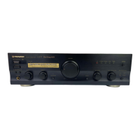
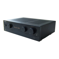
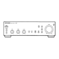
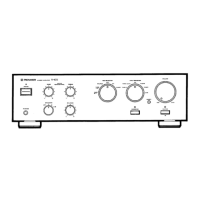
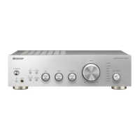
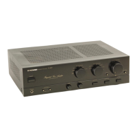
Visual representation of the amplifier's exterior components and their layout.

Exterior Parts Details

Comprehensive list of external parts with part numbers and model variations.

Schematic Diagram

Overall Connection Diagram

Diagram illustrating the main interconnections between major circuit blocks.

Front L and Volume Assemblies Diagrams

Detailed schematic for the front panel, volume, and related circuits.

Front R, AC Primary, Headphone, and Power SW Assemblies Diagrams

Schematics for front R panel, AC power, headphone, and power switch sections.

PCB Connection Diagram

AF Assembly Connection Diagram

PCB layout showing component and connector positions for the AF assembly.

Front L and Volume Assembly Connection Diagrams

PCB layouts for front L and volume control assemblies, detailing component placement.

Front R Assembly Connection Diagram

PCB layout illustrating the arrangement of components on the front R assembly.

AC Primary, Headphone, and Power SW Assembly Connection Diagrams

PCB layouts for AC primary, headphone, and power switch assemblies.

PCB Parts List

Whole PCB Assemblies List

A list of major PCB assemblies and their corresponding part numbers by model type.

AF Assembly Components

Detailed list of semiconductor, coil, capacitor, and resistor parts for the AF assembly.

Front L and Volume Assembly Components

Parts list for the Front L and Volume assemblies, including semiconductors and capacitors.

Front R, Headphone, Power SW, and AC Primary Assembly Components

Parts lists for Front R, Headphone, Power SW, and AC Primary assemblies.

Adjustments

Idle Current Adjustment Procedure

Step-by-step guide for adjusting the amplifier's idle current with specific voltage targets.

General Information

IC Information and Pinouts

Details on integrated circuits, including pin assignments and functions for the remote control microcomputer.

Block Diagram Overview

Functional block diagram illustrating the signal flow and major circuit interconnections.

Panel Facilities and Specifications

Rear Panel Layout and Terminals

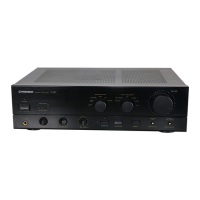
Identification and description of connectors and controls on the rear panel.

Front Panel Controls Overview

Explanation of the power, standby, volume, and sensor controls on the front panel.

Front Panel Input and Tone Controls

Details on input selection, balance, tone controls, loudness, and speaker selection.

Remote Control Unit Functions

Description of buttons and functions available on the remote control unit.

Technical Specifications

Detailed technical data including power output, sensitivity, frequency response, and dimensions.

Related product manuals