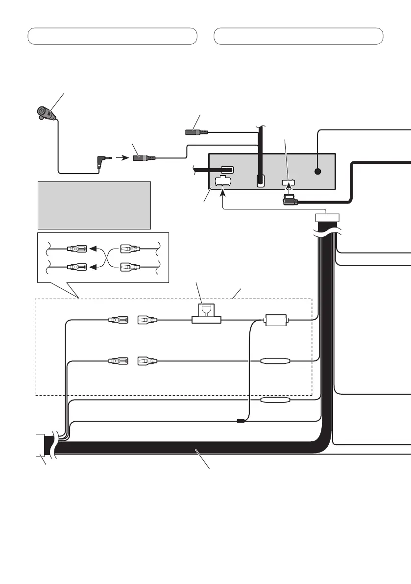
26 pin cable (Supplied with Navigation unit)
Insert the 26 pin cable in the direction
indicated in the figure.
Navigation unit
(AVIC-F220 (sold
separately)).
Notes:
· Change the initial setting of this unit (refer to the Operation Manual). The
subwoofer output of this unit is monaural.
· When using a subwoofer of 70 W (2 Ω) , be sure to connect with Violet and
Violet/black leads of this unit. Do not connect anything to Green and
Green/black leads.
Connection method
1. Clamp the lead.
2. Clamp firmly with
needle-nosed pliers.
Note:
· The position of the parking brake switch depends on the vehicle model. For details, consult the vehicle
Owner’s Manual or dealer.
Yellow/black
If you use an equipment with Mute function, wire this lead to the Audio Mute lead on
that equipment. If not, keep the Audio Mute lead free of any connections.
Light green
Used to detect the ON/OFF status of the parking brake.
This lead must be connected to the power supply side of
the parking brake switch.
Blue/white
Connect to system control
terminal of the power amp
(max. 300 mA 12 V DC).
Blue/white (6*)
Connect to auto-antenna relay control
terminal (max. 300 mA 12 V DC).
The pin position of the ISO
connector will differ depending on
the type of vehicle. Connect 5* and
6* when Pin 5 is an antenna control
type. In another type of vehicle,
never connect 5* and 6*.
Blue/white (5*)
Ground side
Power supply side
Parking brake
switch
Speaker leads
White: Front left
White/black: Front left
Gray: Front right
Gray/black: Front right
Green: Rear left or subwoofer
Green/black: Rear left or subwoofer
Violet: Rear right or subwoofer
Violet/black: Rear right or subwoofer
ISO connector
Note:
In some vehicles, the ISO connector may be divided into
two. In this case, be sure to connect to both connectors.
Note:
Depending on the kind of vehicle,
the function of 2* and 4* may be
different. In this case, be sure to
connect 1* to 4* and 3* to 2*.
1*
3*
2*
4*
Yellow (2*)
Back-up
(or accessory)
Yellow (1*)
Connect to the constant 12 V
supply terminal.
Connect leads of the same
color to each other.
Fuse resistor
Red (4*)
Accessory
(or back-up)
Red (3*)
Connect to terminal controlled by
ignition switch (12 V DC).
Black (chassis ground)
Connect to a clean, paint-free metal location.
This product
Microphone input Jack (MIC)
(AVH-5200BT only)
Microphone (supplied)
(AVH-5200BT only)
Antenna input
Fuse resistor
Orange/white
Connect to lighting switch terminal.
Fuse resistor
Violet/white
Of the two lead wires connected to the back lamp, connect the one in which the
voltage changes when the gear shift is in the REVERSE (R) position. This connection
enables the unit to sense whether the car is moving forwards or backwards.
4 m
Fuse (10 A)
Please contact your dealer to inquire
about the connectable navigation unit.
Tuner box (supplied)
Antenna cable (supplied)
80 cm
80 cm
Wired remote input (WIRED REMOTE INPUT)
Hard-wired remote control adaptor can be
connected (sold separately).
RGB input
17 cm
17 cm
 Loading...