EasyManua.ls Logo

Pioneer CLD-2850 Service Manual

Pioneer CLD-2850
63 pages
To Next Page IconTo Next Page
Page #1 background imageLoading...
Page #1 background image
Service
@
PIONEER’
The
Art
of
Entertainment
PAZEVUED
ORDER
NO.
CD._CDV
LD
PLAYER
CLD-
CLD-2850
HAS
THE
FOLLOWING
:
ARP2787
Power
Requirement
@
This
manual
is
applicable
to
CLD-
2850/WEZ
and
WB.
For
WB
type,
refer
to
page
75.
CONTENTS
1.
SAFETY
INFORMATION
-
2.
DISASSEMBLY
3.
EXPLODED
VIEWS,
PACKING
AND
PARTS
LIST
-
4,
BLOCK
DIAGRAM
5.
SCHEMATIC
AND
PCB
CONNECTION
DIAGRAMS
---
6.
PCB
PARTS
LIST
--
7.
ADJUSTMENTS
-
8.1C
INFORMATION
--
9.
FOR
WB
TYPE---
10.
CONNECTIONS
-
11.
PANEL
FACILITIES
12.
SPECIFICATIONS
----
PIONEER
ELECTRONIC
CORPORATION
=
4-1,
Meguro
1-Chome,
Meguro-ku,
Tokyo
#53,
Japan
PIONEER
ELECTRONICS
SERVICE
INC.
P.O.
Box
1760,
Long
Beach,
California
90801
U.S.A.
PIONEER
ELECTRONICS
OF
CANADA,
INC.
300
Allstate
Parkway
Markham,
Ontario
L3R OP2
Canada
PIONEER
ELECTRONIC
[EUROPE]
N.V._Haven
1087
Keetberglaan
1,9120
Melsele,
Belgium
PIONEER
ELECTRONICS
AUSTRALIA
PTY.
LTD.
178-184
Boundary
Road,
Braeside,
Victoria
3195,
Australia
TEL:
[03]
$80-9911
©
PIONEER
ELECTRONIC
CORPORATION
1993
IFO
JUNE
1993
Printed
in
Japan
Question and Answer IconNeed help?

Do you have a question about the Pioneer CLD-2850 and is the answer not in the manual?
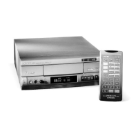
Pioneer CLD-2850 Specifications

General IconGeneral
TypeLaserDisc Player
Remote ControlYes
Laser TypeSemiconductor Laser
Laser Power5 mW
Number of Channels2
Disc Formats SupportedCD
Video OutputComposite Video
Audio OutputAnalog, Digital
Video Output Level1.0 Vp-p
Frequency Response4 Hz - 20 kHz
Harmonic Distortion0.003%
Output Voltage2 V

Summary

1. SAFETY INFORMATION

Laser Warnings and Label Checks

Details laser radiation warnings, safety labels, and precautions for safe operation.

2. DISASSEMBLY PROCEDURES

Disc Tray and Clamper Assembly Removal

Steps for removing the disc tray and clamper assembly.

Carriage Assembly and Cam Gear Installation

Procedures for removing the carriage and installing the cam gear.

Mechanical Component Installation Steps

Detailed steps for installing various mechanical components.

Final Mechanical Assembly Cautions

Important notes and procedures for final mechanical assembly.

3. EXPLODED VIEWS AND PARTS LISTS

Exterior Section Parts

Exploded view and parts list for exterior components.

Front Panel Section Parts

Exploded view and parts list for the front panel assembly.

Top View Section Parts

Exploded view and parts list from the top view.

Clamper Section Parts

Exploded view and parts list for the clamper mechanism.

Base Section Parts (1)

Exploded view and parts list for the base section (part 1).

Mechanism Assembly Parts

Exploded view and parts list for the main mechanism assembly.

Carriage Assembly Parts

Exploded view and parts list for the carriage assembly.

Packing List

List of parts included in the product packaging.

4. BLOCK DIAGRAMS

5. SCHEMATICS AND WIRING DIAGRAMS

Schematic and PCB Connection Diagrams

Overall schematics and PCB connection diagrams for the unit.

Overall Wiring Diagram

Comprehensive wiring diagram showing interconnections between major assemblies.

SYPS Assembly Diagram

Schematic and wiring diagram for the SYPS assembly.

Pickup and CNNB Assemblies Diagrams

Diagrams for the pickup and CNNB assemblies, including signal routes.

FTS and Audio Section Diagrams

Schematics and diagrams for the FTS and audio signal processing sections.

Video and TBC Section Diagrams

Schematics and diagrams for the video and TBC (Time Base Correction) sections.

Main Board Assembly Diagrams

Schematics and diagrams for the main board assembly.

DSCB Assembly Diagram

Schematic and wiring diagram for the DSCB assembly.

6. PCB PARTS LIST

7. ADJUSTMENTS

Required Jigs and Instruments

List of tools and equipment needed for performing adjustments.

Test Mode Operation and Key Controls

Guide to entering, using, canceling test mode, and key operations.

Main Board Assembly Adjustment Summary

Summary of adjustments for the main board assembly, with specific points and procedures.

Preparations and Precautions for Adjustment

Essential steps and warnings before performing adjustments.

8. IC INFORMATION

9. FOR WB TYPE

Contrast of Miscellaneous Parts

Highlights differences in parts between WB and WEZ/CLD-2850 models.

10. CONNECTIONS

11. PANELFACILITIES

12. SPECIFICATIONS

General System Specifications

Overall system details including laser, power, dimensions, and operating conditions.

Disc Specifications

Details on LaserVision and Compact Disc playback capabilities and times.

Video and Audio Characteristics

Specifications for video output and audio characteristics.

Other Terminals and PIN Assignment

Information on external terminals and their pin assignments.

Accessories List

List of items included with the product.

REMOTE CONTROL FUNCTIONS

Related product manuals