EasyManua.ls Logo

Pioneer CT-1060W Service Manual

Pioneer CT-1060W
72 pages
To Next Page IconTo Next Page
Page #1 background imageLoading...
Page #1 background image
VY)
PIONEER’
Service
CIRCUIT
DESCRIPTIONS
REPAIR
&
ADJUSTMENTS
ARP-782-0
©
CT-S77W
[BK]
STEREO
DOUBLE
CASSETTE
TAPE
DECK
CT-lI0o60W
CT-IO6GOW
(BK)
CT-S77W
CT-S77W
(BK)
e
CT-S77W
is
the
same
as
the
CT-1060W
except
for
the
exterior
design.
©
CT-1060W
[BK]
is
black
version
of
CT-1060W.
e
CT-S77W
[BK]
is
black
version
of
CT-S77W.
©
Models
CT-1060W
(silver),
CT-1060W
[BK]
(black),
CT-S77W
(silver)
and
CT-S77W
[BK]
(black)
come
in
versions
distinguisehd
as
follows:
Applicable
model
CT-1060W
CT-1060W{BK
]
CT-S77W
CT-S77W([BK]
Power
requirement
Destination
|
AC120V
only
U.S.A.
AC120V
only
Canada
AC220V
(240V)*
European
con
tinent
AC240V
(220V)*
United
Kingdom
AC240V
(220V)*
Australia
AC120/220/240V
(switchable)
General
market
AC120/220/240V
(switchable)
US,
Military
*Change
the
primary
wiring
of
the
power
ts-ansformer,
e
This
service
manual
is
applicable
to
the
KU,
HEM,
HB,
HP,
D
and
D/G
types.
¢
As
to
the
HEM,
HB,
HP,
D
and
D/G
types,
please
refer
to
pages
90
92.
e
As
to
the
KC
type,
please
refer
to
the
additional
service
manual
(ARP-783-0).
¢
Ce
manual
d’instruction
se
refére
au
mode
de
réglage
en
francais.
(p.
40
p.
46)
e
Este
manual
de
servicio
trata
de!
método
ajuste
escrito
en
espanol,
(p.
47
p.
54)
PIONEER
ELECTRONIC
CORPORATION
4-1,
Meguro
1-Chome,
Meguro-ku,
Tokyo
153,
Jape
PIONEER
ELECTRONICS
(USA)
INC.
P.O.
Box
1760,
Long
Beach,
California
30801
U.S.A.
TEL:
(B00)
421-1404,
{800)]
237-0424
PIONEER
ELECTRONIC
[EUROPE]
N.V.
Keetbergiaan
1,
2740
Beveren,
Belgium
TEL:
03/775:28-08
PIONEER
ELECTRONICS
AUSTRALIA
PTY.
LTO.
178-184
Boundary
Road,
Braeside,
Victoria
3195,
Australia
TEL:
(03)
580-8911
YH
©APR.
1985
Printed
in
Japan
ORDER
NO.
Question and Answer IconNeed help?

Do you have a question about the Pioneer CT-1060W and is the answer not in the manual?

Pioneer CT-1060W Specifications

General IconGeneral
Track System4-track, 2-channel stereo
MotorDC servo motor
Total Harmonic Distortion1.0%
Output0.5V (line)
TypeAuto Reverse Double Compact Cassette Deck
Heads1 x Playback, 1 x Record/Playback, 1 x Erase
Dimensions420 x 125 x 280mm
Signal to Noise Ratio75dB (Dolby C)

Summary

Safety Information

Safety Precautions and Leakage Current Check

Guidelines for customer/technician safety and leakage current testing.

Product Safety Notice

Information on special safety characteristics of components and replacement parts.

Specifications

Front Panel Facilities

Front Panel Operation

Dolby NR and Tape Selector Controls

Controls for Dolby NR and tape type selection.

Disassembly Procedures

Tape Transport Unit Disassembly

Step-by-step instructions for disassembling the tape transport unit.

Main Unit Disassembly

Component Removal

Parts Location Diagrams

Front Panel Views (CT-1060W & CT-S77W)

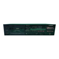
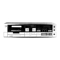
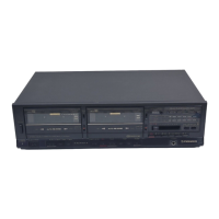
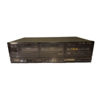
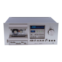
Diagrams showing parts location on the front panels of both models.

Exploded Views and Parts Lists

Exterior Components

Parts List of Exterior Components

List of exterior components with part numbers and key numbers.

Tape Transport Unit (Deck 1) Exploded View

Tape Transport Unit (Deck 1) Parts List

Tape Transport Unit (Deck II) Parts List

Tape Transport Unit (Deck II) Exploded View

P.C. Board Connection Diagrams

Main and Tape Transport Unit Connections

Diagrams showing signal connections between main unit and tape transport units.

Schematic Diagrams

Electrical Parts List

Adjustments

Mechanical Adjustments

Procedures for mechanical adjustments before electrical calibration.

Pinch Roller and Reel Torque Adjustment

Procedures for adjusting pinch roller pressure and reel base torque.

Tape Speed Adjustment

Procedure for adjusting tape playback speed for both decks.

Electrical Adjustments

Adjustment Conditions and Test Tapes

Prerequisites, conditions, and test tapes for electrical adjustments.

Overview of Adjustments

List of electrical adjustments required for Deck I and Deck II.

Deck I Electrical Adjustments

Head Azimuth and Playback Equalizer

Procedures for Deck I head azimuth adjustment and playback equalizer check.

Playback Level and Time Constant Adjustment

Procedures for Deck I playback level and time constant switching checks.

Deck II Electrical Adjustments

Head Azimuth, Equalizer, and Level Adjustments

Procedures for Deck II head azimuth, equalizer, and playback level adjustments.

Level Meter and Frequency Response Adjustments

Procedures for Deck II level meter check and record/playback response adjustment.

Recording and Copy Adjustments

Recording Level Adjustment

Procedure for adjusting recording signal levels for different tape types.

Block Diagram

Circuit Descriptions

Signal Routes

Signal and Indicator Circuit Control

Relay Playback Mode Details

Copy Function Operation

Relay Play 1 Timing Chart

Relay Play 2 Timing Chart

Copy 1 Timing Chart

Copy 2 Timing Chart

Supplements for Specific Model Types

Related product manuals