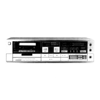
STEREO
CASSETTE TAPE
DECK
(D
rrloNEEFl'
ORDER
NO.
ART-
678-O
9.
SCHEMATIC DIAGRAM
21
10.
PARTS
LIST
.
24
11.
MECHANICALADJUSTMENTS
......
27
al
REGLAGESMECANIOUES....
29
t
AJUSTESMECANICOS
.....31
12. ELECTRICAL
ADJUSTMENTS
33
at
REGLAGESELECTRIOUES...
37
,
AJUSTESELECTRTCOS
....
.......
4.1
I
I
CONTENTS
1.
SPECTFTCATTONS .
.... .
2
2.
FRONTPANELFACILITIES
.....3
3. DISASSEMBLY...
......4
4.
PARTSLOCATION
....6
5.
EXPLODEDVIEWSANDPARTSLIST
.. .. . .
..
8
6.
PACKING
14
7.
BLOCKDIAGRAM
...... 15
8.
P.C.
BOARDCONNECTION DIAGRAM
.... ..
17
lr
rl
f.-r
This
service manual is
applicable to the
KU type. For
servicing
of
the
other types,
please
refer
to the
addi-
tional
service manual.
For
the mechanism &
circuit descriptions,
pleæe
refer
to the
supplement of
model
CT-5 service manual
(ARP-002).
Ce
manuel d'instruction
se
refère au
mode
de
réglaç, en
français.
Este manual de
servicio
trata
del
método
de
ajuste escrito en espaffol.
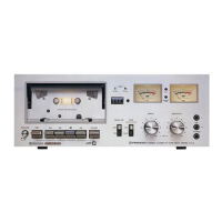
MODEL
CT-5 COMES IN
SIX
VERSIONS
DISTINGUISHED
AS
FOLLOWS:
Type
Volatge
Remarks
KU 120V
only
U.S.A. model
KC 120V
only
Canada model
HE
22OY
and 24OV
(switchable)
Europe
model
HB
22OY and 240V
(switchable)
U.K. model
HP
22OV and 240V
(switchable)
Australia model
D 12OV,22OV
and
240V
(switchable)
General
export model
PICINEEF| ELECTF|CINIC CCIFIFOFIATICIN
4-1,
MesuFo
't-chome,
Mesurc-ku. Tokyo
1s3,
Jep€n
1J.5.
PlCt
lEEFl
EL.EgfFrcI\laCB
OG'FIPC'F|ATIGIN 85 Oxfond Onive,
Moonactrre.
New Je€ey O7O74. U.S.A
IIICINEEFI
H.ESfF|CINIC
(EUFICTPEI
N.V. LuiÈh€gen-Hêven
9,
2O3O
Antwenp.
Belgium
FfCINEEFI
ELEgfFrclNlCA AUBTF|ALIA FÎY. L1E.
178-1EJ4
E}oundary
F|oad, Ê|neesrde, VEÈonia
3195, AusEnalE
YP
@MAY 198I Printed
in
lapan