C)
rrloNeerl'
aa
ORDER
NO.
ARP-I47-O
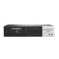
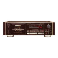
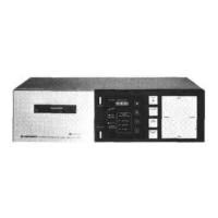
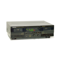
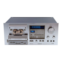
STEREO CASSETTE
TAPE DECK
cT-73cI
o
This
service manual is applicable to
the KU, HE, HB, HP and D types,
o
Ce manuel d'instruction
se refdre au mode de r6glage.
en
fangais.
.
Este
manual de
servicio trata del m6todo de
ajuste escrito en espafrol.
CONTENTS
14
to
18
1.
SPECTF |CAT|ONS
.....
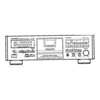
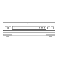
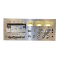
2. FRONT PANEL
FACILITIES
3. BLOCK
DIAGRAM
4.
CIRCUIT DESCRIPTIONS
5. DISASSEMBLY
......
6. PARTS
LOCATION
7.
EXPLODEO VIEWS
AND PARTS LIST
. .
PICINEEFI ELECTFICINIC
CCIFIPCIF|ATION a-r,
Mesu.o 1 cho.ne. Mesu.o-ku, rokyo.1s3.
Jape.
PIC,NEEFI
ELECTFIC,NICB
IUAAI
lNC.
'1925
E.
Dom,nguez St.,
Long E]each. Ca
ronnra
9OB1O U.S.A.
PIC'NEEFI ELECTFIC'NIC
IEUFIC'PEI
N.v. Lu thagen
Hsven
9, 2O3O Antwe.p, Betg,um
FIC'NEEFI ELECTFIG,NICA
AUATF|ALIA PTY. LTEI.
'178-184
Boundanv Fload.
E!.aesde, V,cto.r6 3195, Ausr.atia
8. E LECTRICAL
PARTS LIST.
9.
PACKING
10.
P.C.
BOARD
CONNECTION
DIAGRAM
11. SCHEMATIC DIAGRAM
12. ADJUSTMENTS
....
REGLAGE
AJUSTE
.
25
z6
2S
J5
37
44
51
MODELCT.T3OCOMES
IN FIVE VERSIONS
DISTINGUISHED
AS
FOLLOWS:
Typ. Voltrg€
Remarka
KU
120V only
U.S.A. model
HE
22OV and 24OV
{Switchablel Europe model
HB
22OV a^d 24OV
(Swirchable)
United
Kingdom model
HP
22OV a
d 24OV
(Switchable)
Australia
model
D 12OV 22OV and
24OV
(Switchable)
Gengral export
model
YZ
@
[4AY
1982
Prinred
in
Japan