This document is a service manual for the Pioneer DEH-3250UB, DEH-3250UB/XNES, DEH-3290UB/XNID, and DEH-2200UB/XSEWS CD Receiver models. It provides detailed information for maintenance and repair, including exploded views, parts lists, schematic diagrams, and PCB connection diagrams.
Function Description:
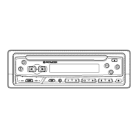
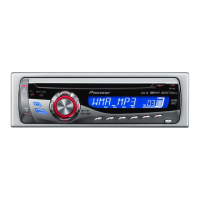
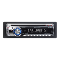
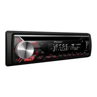
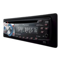
These devices are CD receivers designed for in-car audio systems. They support playback of CDs and feature a USB input for connecting external devices, allowing users to enjoy music from various sources. The "UB" in the model names likely indicates a USB connection. The devices are equipped with a tuner for radio reception and an amplifier for audio output. Some models also support "Plays Windows Media™," indicating compatibility with Windows Media Audio (WMA) files. The presence of "Digital Audio" and "Compact Disc Digital Audio Text" logos suggests support for high-quality digital audio playback and display of CD text information.
Important Technical Specifications:
The manual provides a comprehensive list of parts and their specifications, which are crucial for repair and maintenance. While specific performance metrics like power output or frequency response are not explicitly stated in the provided excerpts, the detailed parts lists for various units (Tuner Amp Unit, CD Core Unit, Keyboard Unit, Panel Unit) indirectly reveal the technical architecture.
For instance, the "Tuner Amp Unit" parts list includes various ICs, transistors, diodes, and resistors, indicating the components responsible for radio reception and audio amplification. The "CD Core Unit" lists components like ICs and transistors specific to CD playback. The "Keyboard Unit" and "Panel Unit" parts lists detail the components for user interface and display.
The electrical parts lists specify resistor values (e.g., RS1/4S4561J, RS1/10SR102J), capacitor values (e.g., CKSBYB105K6R3, CKSBYB104K16), and other component types (e.g., IC, transistor, diode, LED, connector). These specifications are vital for replacing faulty components with correct equivalents.
Usage Features:
The CD receivers offer standard features expected from car audio systems:
- CD Playback: Supports audio CDs.
- USB Connectivity: Allows connection of USB devices for music playback. This is a key feature highlighted by the "UB" in the model names.
- Radio Tuner: For receiving AM/FM broadcasts.
- Audio Output: Provides rear and front audio outputs, likely RCA pre-outs, for connecting external amplifiers.
- Wired Remote Control: A connector for a wired remote control is present, allowing for convenient operation from the steering wheel or other locations.
- Antenna Input: Standard input for a car radio antenna.
- Display: The "LCD Module" in the Keyboard Unit suggests an LCD display for showing track information, radio stations, and other relevant data.
- User Interface: Buttons for various functions like "UP," "LEFT," "RIGHT," "DOWN," "BAND," "DISP," "REGION," and "LIST" are indicated on the Keyboard Unit PCB, providing intuitive control.
Maintenance Features:
The service manual is primarily a maintenance and repair guide, offering extensive features for technicians:
- Exploded Views and Parts Lists: These sections (e.g., "EXPLODED VIEWS AND PARTS LIST," "ELECTRICAL PARTS LIST") provide visual breakdowns of the device and detailed lists of all components, including their part numbers and descriptions. This is essential for identifying and ordering replacement parts.
- CD Mechanism Module: A dedicated section (Page 42) details how to fasten and replace the front panel, including attaching and replacing holders, and fixing the unit using screws. This is a common maintenance procedure for CD players.
- Schematic Diagrams: The "SCHEMATIC DIAGRAM TUNER AMP UNIT" (Page 10 onwards) provides detailed circuit diagrams for various sections like the CD, CD VD, Tuner, USB, Grill, EVOL, System Micro, AMP, and IC Regulator. These diagrams are critical for troubleshooting electrical issues and understanding the signal flow.
- Symbol Indications: The diagrams include notes explaining symbols for resistors, capacitors, and non-differentiated components, aiding in circuit analysis.
- NM (No Mount) Indications: Components marked "NM" are not mounted, which is important for understanding variations between models or revisions.
- Voltage and Waveform Information: Some diagrams include voltage values (e.g., "CDX588L-09.0db~19.4 dbµ") and waveform indications (red arrows), which are invaluable for diagnosing circuit malfunctions.
- PCB Connection Diagrams: Sections like "PCB CONNECTION DIAGRAM KEYBOARD UNIT" and "PANEL UNIT" show the layout of components on the printed circuit boards and their interconnections. This helps in locating components physically and verifying connections.
- Viewpoints: The diagrams specify "SIDE A" and "SIDE B" views of the PCBs, ensuring correct orientation during repair.
- Component Identification: The diagrams help in identifying specific components on the PCB, such as connectors (CN1, CN2, CN831) and various switches and LEDs.
- Diagnosis Section: The "DIAGNOSIS CONNECTOR FUNCTION DESCRIPTION" (Page 9) provides a diagram of the rear panel connectors, including pin assignments for the wired remote control and audio outputs. This is crucial for testing external connections and diagnosing communication issues.
- Pin Descriptions: Each pin of the wired remote control connector is described (e.g., FL+, FR+, TEL, NC, B.REM, B.UP, GND), allowing technicians to verify signals.
- Model-Specific Information: The manual clearly distinguishes between different models (DEH-2200UB/XSEWS, DEH-3250UB/XSUR, DEH-3250UB/XNES, DEH-3290UB/XNID) in the parts lists and diagrams, ensuring that the correct components and procedures are used for each specific variant.
- Important Notes for PCB Diagrams: Instructions are provided to ensure that all necessary parts for the LCD are included when ordering a PCB and to cross-reference with schematic diagrams. This emphasizes the importance of thoroughness in maintenance.
- Component Marking: The manual notes that some components are omitted or have different markings, which is important for identifying the correct parts. It also highlights that the mark found on some component parts indicates the safety factor of the part, and that replacement parts should be identical in designation. This ensures safety and proper functionality after repair.