Do you have a question about the Pioneer DEH-4090MP and is the answer not in the manual?
Safety precautions for servicing personnel, including caution regarding laser diode.
Guidelines for safe product handling and repair procedures, including parts usage and soldering.
Procedures for optimizing product performance and confirming specifications.
Guidance on using specified lubricants, adhesives, and replacement parts.
Instructions for cleaning specific parts like optical pickups and lenses.
Procedures for protecting the product during transit via shipping mode or screws.
General safety and handling precautions for service technicians, including power off, IC handling, and component reuse.
Guidelines for using lead-free solder, soldering iron temperature, and solder types.
Technical specifications for the DEH-4090MP/XN/ID model, including general, audio, CD, FM, and AM tuner.
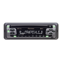
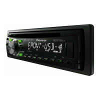
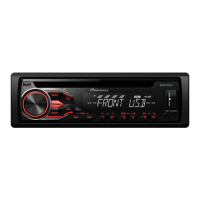
Descriptions of the controls on the head unit, including SRC/OFF, DISP/BACK/SCROLL, MULTI-CONTROL, etc.
Information on how to operate the unit using the remote control.
Instructions for attaching holders to the front panel for mounting.
Procedure for reattaching the front panel to the main unit.
Step to orient the holders into their upright positions.
Securing the front panel to the unit using designated fixing screws.
Essential checks to perform after service to ensure product quality and functionality.
Diagrams showing the locations of main PCBs within the unit.
Lists of specialized jigs and greases used for service and maintenance.
Prescribed cleaning tools for product maintenance before shipping.
Flowchart illustrating the operational sequence and decision points for diagnosis.
Explanation of how error codes are displayed and indicated on the unit.
Examples of error code displays on different LCD capabilities.
Table detailing error codes, their classes, displayed codes, and potential causes.
Procedure for entering and operating the CD Test Mode for diagnostics and adjustments.
Step-by-step guide to removing the keyboard unit from the front panel assembly.
Instructions for detaching and removing the holder mechanism.
Procedure for detaching the main case and front panel.
Steps to remove the CD mechanism module from the unit.
Procedure for removing the panel assembly.
Steps to detach and remove the panel unit.
Instructions for removing the tuner amplifier unit.
Detailed steps for removing the upper and lower frames of the mechanism, including springs and screws.
Precautions and test mode procedures for adjusting the CD mechanism module.
Exploded view and parts list for the packing and accessories.
List of parts included in the packing section of the product.
Comparison table of parts for DEH-4090MP/XN/ID and DEH-6010MP/XN/UR models.
Parts list for the exterior components of the unit (Part 1).
Comparison table of parts for DEH-4090MP/XN/ID and DEH-6010MP/XN/UR models.
Parts list for the exterior components of the unit (Part 2).
Comparison table of parts for DEH-4090MP/XN/ID and DEH-6010MP/XN/UR models.
Parts list for the CD mechanism module components.
Overall connection diagram illustrating the system's main component interconnections.
Oscilloscope waveforms for CD core unit signals during various operations.
Oscilloscope waveforms for various operations like search, eject, and jump.
PCB connection diagram for the Tuner Amp Unit.
List of chip resistors with their circuit symbols, part numbers, and locations.
List of chip capacitors with their circuit symbols, part numbers, and locations.
List of miscellaneous components like ICs, transistors, diodes, and inductors.
Detailed list of resistors with circuit symbols, part numbers, and locations.
Detailed list of capacitors with circuit symbols, part numbers, and locations.
Continued list of resistors with circuit symbols, part numbers, and locations.
Continued list of capacitors with circuit symbols, part numbers, and locations.
List of miscellaneous components including LEDs and switches.
Final list of resistors with circuit symbols, part numbers, and locations.
Final list of capacitors with circuit symbols, part numbers, and locations.
Final list of resistors with circuit symbols, part numbers, and locations.
Final list of capacitors with circuit symbols, part numbers, and locations.
List of miscellaneous parts like pickup unit and motors.
| Brand | Pioneer |
|---|---|
| Model | DEH-4090MP |
| Category | Car Stereo System |
| Language | English |