
 Need help?
Do you have a question about the Pioneer DEH-5/XU/US and is the answer not in the manual?
Identifies the service manual for DEH-5/XU/UC and related models, including order number.
Manual intended for qualified techs; warnings on product safety, chemicals, and proper servicing.
Explains important symbols and practices for product safety, adjustments, cleaning, shipping, and parts.
Emphasizes powering off before disassembly and ESD protection for the pickup unit.
Highlights checking grating after pickup replacement and notes on test mode availability.
Covers power source, dimensions, output power, impedance, and audio features.
Details FM/AM tuner performance and CD player system specifications.
Covers power, dimensions, output, and 3-band EQ for DEH-15/1500 models.
Details tuner performance and CD player specs for DEH-15/1500 models.
Illustrates packing contents and lists associated parts like manuals and accessories.
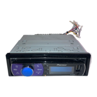
Visual breakdown of the exterior parts of the DEH-5/XU/UC model.
Continues the visual breakdown of the DEH-5/XU/UC exterior components.
Itemized list of external parts for the DEH-5/XU/UC model with part numbers.
Visual breakdown of exterior parts for DEH-15/XU/UC and DEH-1500/XU/UC models.
Itemized list of external parts for DEH-15/XU/UC and DEH-1500/XU/UC models.
Illustrates the arrangement of parts within the CD mechanism module.
Lists all components of the CD mechanism module with their part numbers.
Shows the functional blocks and connections within the tuner amp unit.
Details system controller, power amp, regulators, and keyboard unit functional blocks.
Functional block diagrams for tuner amp and CD units of DEH-15/1500 models.
Block diagrams for system controller, power amp, and keyboard units of DEH-15/1500.
Shows overall system connections for DEH-5/XU/UC, referencing detailed pages.
Detailed schematic of the tuner amplifier circuitry including power and control sections.
Continues the schematic of the tuner amplifier, showing signal paths and component connections.
Final part of the tuner amp unit schematic, detailing specific signal processing and control lines.
Completes the tuner amp unit schematic, showing connections to power, audio, and remote control.
Schematic for system controller, power supply regulators, and remote control interface.
Illustrates the placement of components and connectors on the keyboard unit PCB.
Shows the electronic circuit for the keyboard unit, including buttons, LCD, and controller.
Schematics for pickup unit, motor drivers, and CD core unit control logic.
Detailed schematic for RF amplifier, servo system, DSP, and DAC/LPF sections.
Displays waveforms for CD loading, initial setup, source selection, and signal levels.
Illustrates waveforms for track search, playback modes, audio output, and eject operations.
Shows component placement and routing on the Tuner Amp Unit PCB, Sides A and B.
Continues the PCB layout for the Tuner Amp Unit, Side A, showing more component placements.
Further details of the Tuner Amp Unit PCB layout, Side A.
Component placement and routing on the Tuner Amp Unit PCB, Side B.
Component layout for the Keyboard Unit PCB, Sides A and B.
Component placement and routing on the CD Mechanism Module PCB, Side A.
Component placement and routing on the CD Core Unit PCB, Side B.
Lists miscellaneous ICs, transistors, diodes, inductors, arresters, and resistors for the Tuner Amp Unit.
Lists capacitors, miscellaneous parts, and resistors for DEH-15/1500 Tuner Amp Units.
Lists parts for the Keyboard Unit, including IC, diodes, LEDs, resonator, and lamps.
Lists capacitors, resistors for CD Core Unit, and parts for Keyboard Unit.
Lists capacitors and resistors for the CD Core Unit.
Lists miscellaneous parts for the CD Mechanism Module, including pickup and motor units.
Important safety notes, reference voltage, and instructions for entering/exiting test mode for CD adjustment.
Explains the goal of grating check, mal-adjustment symptoms, and the required method/equipment.
Step-by-step guide to checking grating, including phase difference limits and wobble observation.
Visual examples of grating waveforms at various angles (0° to 90°).
Explains error message display methods and provides a list of CD error codes with descriptions.
Instructions for removing the unit case and the CD mechanism module.
Steps for removing the grille assembly and the tuner amp unit.
Instructions for assembling the keyboard unit, including tabs and contact considerations.
Guidelines for holding the unit and removing upper/lower frames, dampers.
Instructions for detaching the guide arm assembly, including spring and screw removal.
Procedure for removing the CD core unit, including solder and clamp mode precautions.
Steps to remove the roller arm assembly, including springs and E-shaped rings.
Instructions for removing the pickup unit, washers, holders, and feed screw.
Steps to remove the load carriage motor assembly and its holder.
Details the pin functions for the rear panel connector, including audio, power, and remote control.
Lists pin numbers, names, I/O, and functions for the PE5330A/PE5331A ICs.
Continues PE5330A/PE5331A pin functions, including MOS type handling notes.
Details the pin functions for the PD6340A IC, covering LCD segment and common outputs.
Lists pin functions for UPD63712GC IC, covering LD, PD, RF, and data signals.
Continues UPD63712GC pin functions, including EFM, asymmetry, RF, and audio signals.
Details pin functions for the BA5996FP IC, related to preamplifiers and power stages.
Explains symbols and I/O for tuner unit pins, covering antenna, power, and signal levels.
Shows segment and common pin connections for the DEH-5/XU/UC LCD.
Illustrates segment and common pin connections for the DEH-15/XU/UC LCD.
Shows segment and common pin connections for the DEH-1500/XU/UC LCD.
Illustrates the sequence of operations during power-on, including sensor checks and communication.
Specifies tools and procedures for cleaning CD pickup lenses before shipping.
Explains the function of each button on the head unit, including CLOCK, EJECT, AUDIO, and SOURCE.
Guides on powering on, selecting sources, tuning radio, and storing presets.
Instructions for CD playback, including track skipping, random/repeat play, and pause.
Guides on connecting rear audio, power amplifier, and speaker configurations.
 General
| Channels | 4 |
|---|---|
| Max Power Output | 50 W x 4 |
| CD Playback | Yes |
| MP3 Playback | Yes |
| WMA Playback | Yes |
| Equalizer | Yes |
| Detachable Face | Yes |
| Remote Control | Yes |
| DIN Size | 1 DIN |
| Tuner | AM/FM |
| USB Input | Yes |
| AUX Input | Yes |
| EQ Bands | 5 |
| Preamp Voltage | 2V |
| Preamp Outputs | 3 |



 To Next Page
