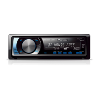
Do you have a question about the Pioneer DEH-P700BT XN and is the answer not in the manual?
| Bluetooth | Yes |
|---|---|
| USB Port | Yes |
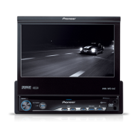
| CD Playback | Yes |
| AM/FM Tuner | Yes |
| DIN Size | Single DIN |
| MP3 playback | Yes |
| WMA playback | Yes |
| AAC playback | Yes |
| Display Illumination | Variable Color |
| Preamp Outputs | 3 (Front, Rear, Subwoofer) |
| Subwoofer Output | Yes |
| AUX input | Yes |
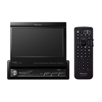
| Remote Control | Yes |
| High-Pass Filter | Yes |
| Low-Pass Filter | Yes |
| Power Output | 50 Watts x 4 |
| RMS Power Output | 22 W |
| Equalizer | 13-Band Graphic Equalizer |
| Steering Wheel Control | Yes |
| Dimensions (W x H x D) | 178mm x 50mm x 160mm |
Contains essential safety warnings, cautions, and precautions for service technicians.
Ensures compliance with regulations and maintains a safe servicing environment.
Details optimum adjustments and characteristic confirmations for product performance.
Specifies the use of correct lubricants and adhesives for repairs.
Outlines proper cleaning methods for optical pickups, lenses, and heads.
Describes setting shipping mode or screws for transit protection.
General guidelines for adhering to safety regulations and handling components during servicing.
Information on using lead-free solder and proper soldering techniques for environmental protection.
Details power source, dimensions, weight, audio output, equalizer, and tuner specifications.
Specifies supported disc types (CD Digital Audio) and content formats (MP3, WMA, AAC, WAV).
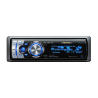
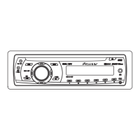
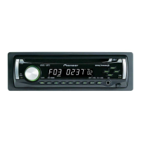
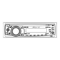
Describes the function of each button and indicator on the head unit's front panel.
Illustrates the overall system connections for audio, power, and accessories.
Confirms problem resolution, media playback, tuner action, and appearance after repair.
Identifies the location and unit number for major PCBs like Tuner, CD Core, Bluetooth, and Antenna.
Details jigs for grating checks, assembly removal, and component cleaning before shipment.
Illustrates the power-on sequence and communication flow with the Grille microcomputer.
Lists error codes, their displayed messages, and potential causes for CD and Bluetooth/telephone errors.
Details the function of each connector on the USB, Rear Output, Antenna, Subwoofer, Front Output, and IP-BUS inputs.
Explains how to enter and use the display test mode, including system version display.
Provides a flowchart and key operations for testing CD mechanism functions like servo control and tracking.
Describes how to reset the microprocessor and Bluetooth wireless technology module for testing.
Highlights cautions when connecting a mobile phone for service site testing and data overwriting.
Specifies confirmation points for simple BT action checks: connection and antenna sensitivity.
Details the operation method for starting the test mode and interpreting the results.
Outlines precautions when using a spectrum analyzer, including antenna connection and cable styling.
States the confirmation objective: checking the output level of the Bluetooth unit.
Step-by-step instructions for removing the keyboard unit from the main assembly.
Details the process of detaching the holder, panel, and case from the unit.
Instructions for disconnecting cables and removing the CD mechanism module.
Guidelines for performing CD adjustment, including test mode entry and cautions regarding voltage and mechanism handling.
Describes the procedure to check the PU unit grating angle for proper tracking and track searching.
Explains how to confirm PCL output and the expected clock signal frequency for troubleshooting.
Lists parts included in the product's packing and accessory kits.
Exploded view diagram showing the exterior parts of the unit.
Exploded view diagram detailing the exterior components and their assembly.
Diagram illustrating the internal components and connections of the CD mechanism module.
Shows the comprehensive system connections between major units like Tuner, USB, Bluetooth, and Panel.
Detailed schematic diagram of the keyboard unit, including LCD driver and button connections.
Schematic diagram for the CD Core Unit, detailing pickup, motor driver, and switch logic.
Schematic diagrams for the Bluetooth Module and Antenna Unit, showing component connections.
Displays oscilloscope waveforms for various test modes, including CD operation and USB/iPod connections.
Illustrates the PCB layout and connector pin assignments for the Tuner Amp Unit.
Shows the PCB layout and component placement for the Keyboard Unit.
Diagram of the CD Core Unit PCB, indicating component locations and connector pinouts.
PCB layout diagram for the Bluetooth Unit, showing component placement and connector CN76.
PCB layout diagrams for the Antenna Unit, showing ANT1101 and ANT1102 connections.
PCB layout diagrams for the Panel Unit, indicating connectors CN1101, CN1972, CN1971, and CN801.