This document is a service manual for the Pioneer F-201L and F-201 FM/AM Digital Synthesizer Tuners, identified by order number ARP2535. It provides detailed information for servicing and maintaining these audio components.
Function Description
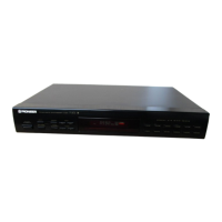
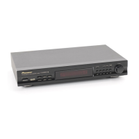
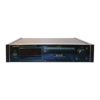
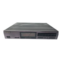
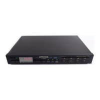
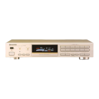
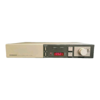
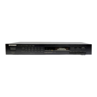
The Pioneer F-201L and F-201 are FM/AM Digital Synthesizer Tuners designed for receiving radio broadcasts. The "L" in F-201L indicates its capability to receive both Medium Wave (MW) and Long Wave (LW) bands, while the F-201 model is limited to MW reception. These tuners utilize digital synthesis for precise and stable tuning.
Important Technical Specifications
The manual outlines various model types and their corresponding power requirements:
- F-201L/HEX1K, HBX1K, HEWZX1K, HEWIX1K: These models require AC220-230V, 240V (switchable) power.
- F-201L/SD: This model requires AC110V, 120-127V, 220V, 240V (switchable) power.
- F-201L/YPW: This model requires AC240V only.
The service manual also references the ARP2007 service manual for the F-227/HEWZ, indicating potential shared components or design principles.
Key components listed in the PCB parts list include:
- TUNER assembly: AWE1172 (F-227/HEWZ), AWZ4139 (F-201L/HEX1K, HBX1K), AWZ4133 (F-201/HEWZX1K), AWZ4134 (F-201/HEWIX1K), AWZ4136 (F-201/SD), AWZ4137 (F-201/YPW).
- REMOCON assembly: AWZ3864 (F-201L/HEX1K, HBX1K, F-201/HEWZX1K, HEWIX1K, SD), AWZ4140 (F-201/YPW). Note that AWZ3864 and AWZ4140 have the same service parts.
- CONTROL assembly: AWP1029 (F-227/HEWZ, F-201/SD, YPW), AWP1040 (F-201L/HEX1K, HBX1K, F-201/HEWZX1K, HEWIX1K). Note that AWP1029 and AWP1040 have the same service parts.
- Fuse (FU1): T400mA/250V (AEK-407 for F-227/HEWZ, AEK-504 for other models).
- AC Power cord: ADG1012 (F-227/HEWZ, F-201/HEWZX1K, HEWIX1K), ADG1049 (F-201L/HEX1K), ADG1087 (F-201L/HBX1K), ADG1051 (F-201/SD), ADG1050 (F-201/YPW).
- FM antenna assembly: ADH1002 (for most models), ADH1004 (for F-201/SD, YPW).
- Ceramic filters: ATF-119, ATF-208.
- ICs: AM/FM IC (LA1265S), MPX IC (AN7470P), PLL IC (LM7001), Regulator IC (MC7812CT).
- Transistors: Various types including 2SC1740S, 2SC1845, 2SA933S, 2SA1529, 2SK246, XDC124ES, XDC143ES, XDA143ES.
- Diodes: 1SS85, 1SS252, S5566, RD6.2ESB2.
- Resistors: Carbon film resistors (RD1/4PM2R2J), and various RD1/8PM types.
- Capacitors: Electrolytic (CEAS series), Ceramic (CKPUY, CKCYB, CKDYF series), Mylar film (CQMA series), Audio film (CFTXA series), Axial (CCPUSL series).
- Ceramic Resonators: ATF1027 (450kHz), ASS1042 (7.2MHz).
- AM RF Tuning Blocks: AXX1012, AXX1013.
- Serial F.E. Module Assemblies: AXQ1003, AXQ1004. Note that AXQ1003 has no service parts.
Usage Features
The tuners are designed for receiving both FM and AM broadcasts. The F-201L model extends this capability to include Long Wave (LW) reception, making it suitable for regions where LW broadcasts are prevalent. The digital synthesizer ensures accurate and stable tuning, a common feature in modern tuners. The presence of a REMOCON (remote control) assembly indicates that the device supports remote operation, enhancing user convenience. Different power requirements and model variations (HEX1K, HBX1K, HEWZX1K, HEWIX1K, SD, YPW) suggest that these tuners were adapted for various international markets and power standards.
Maintenance Features
The service manual is a comprehensive guide for technicians. It includes:
- Contrast of Miscellaneous Parts: A detailed table comparing parts across different models (F-227/HEWZ, F-201L/HEX1K, HBX1K, F-201/HEWZX1K, HEWIX1K, SD, YPW), highlighting commonalities and differences.
- Schematic and PCB Connections Diagrams: Visual representations of the circuit board layouts and wiring, essential for troubleshooting and repair.
- PCB Parts List: An exhaustive list of all components on the printed circuit board, including part numbers, descriptions, and remarks. This list is crucial for identifying and ordering replacement parts.
- Notes on Parts: Important advisories are provided regarding "NSP" (unavailable in Master Spare Parts List) parts, safety-critical components (marked with a triangle), and parts that may have longer delivery times (marked with an asterisk).
- Resistor Ordering: Instructions are given on how to convert resistance values into code form for ordering, including examples for 2-digit and 3-digit effective values.
- Adjustments: Detailed procedures for adjusting the FM and MW tuner sections.
- FM Tuner Adjustment: Steps include adjusting the center frequency (L121), VCO (VR161), and TUNED IND. lighting level (R129) using an FM SG (signal generator), frequency counter, and digital voltmeter. Specific input levels and voltage readings are provided.
- MW Tuner Adjustment: Steps include adjusting MW ANT. tracking (AXX1014), IF (TC101, F121), and TUNED IND. lighting level (R128) using an AM SG (signal generator) and DC voltmeter.
- Diagrams for Adjustments: Visual aids showing connection points (TP-1, TP-2, TP-4, TP-5) and adjustment locations on the PCB.
- Multilingual Support: The manual includes sections for adjustment procedures in French ("REGLAGES") and Spanish ("AJUSTES"), indicating its international scope.
The manual emphasizes the importance of using identical designation parts for replacement, especially for safety-critical components. It also notes that some assemblies (like REMOCON and CONTROL assemblies) may have different part numbers but share the same service parts, simplifying inventory and repair. The "3 Serial F.E. module assembly" (AXQ1003) is explicitly stated to have no service parts, which is an important consideration for repair strategies.