EasyManua.ls Logo

Pioneer F-208RDS User Manual

Pioneer F-208RDS
19 pages
To Next Page IconTo Next Page
Page #1 background imageLoading...
Page #1 background image
ORDER NO.
PIONEER ELECTRONIC CORPORATION 4-1, Meguro 1-Chome, Meguro-ku, Tokyo 153-8654, Japan
PIONEER ELECTRONICS SERVICE, INC. P.O. Box 1760, Long Beach, CA 90801-1760, U.S.A.
PIONEER ELECTRONIC (EUROPE) N.V. Haven 1087, Keetberglaan 1, 9120 Melsele, Belgium
PIONEER ELECTRONICS ASIACENTRE PTE. LTD. 253 Alexandra Road, #04-01, Singapore 159936
PIONEER ELECTRONIC CORPORATION 1999
RRV2114
T – ZZY MAY 1999 Printed in Japan
FM/AM DIGITAL-SYNTHESIZER TUNER
F-208RDS
CONTENTS
1. SAFETY INFORMATION ..................................... 2
2. EXPLODED VIEWS AND PARTS LIST ............... 3
3. BLOCK DIAGRAM AND SCHEMATIC DIAGRAM 6
4. PCB CONNECTION DIAGRAM ......................... 10
5. PCB PARTS LIST .............................................. 14
6. ADJUSTMENT................................................... 15
7. GENERAL INFORMATION ................................ 16
7.1 IC ................................................................. 16
8. PANEL FACILITIES AND SPECIFICATIONS..... 17
THIS MANUAL IS APPLICABLE TO THE FOLLOWING MODEL(S) AND TYPE(S).
Type
Model
F-208RDS
Power Requirement
HYXK/EW O AC220 - 230V
HYXK/GR O AC220 - 230V
HVXK O AC230V
Remarks
STANDBY/ON
RF ATT
MPX
CHARACTER
BAND
CLASS
DIRECT
TUNING
TUNING
MEMORY
12345
6
789
0/10
FM/
AM DIGITAL-SYNTHESIZER TUNER
X¿<?˘BÛ∫
Î
MODE
/SEARCH
MODE
DISPLAY
MODE
EON
EON
Question and Answer IconNeed help?

Do you have a question about the Pioneer F-208RDS and is the answer not in the manual?

Pioneer F-208RDS Specifications

General IconGeneral
Tuning SystemQuartz PLL Synthesizer
Tuning BandsFM, MW
RDSYes
Preset Stations30
Signal-to-Noise Ratio (MW)50 dB
Total Harmonic Distortion (FM)0.3%
Output Level500 mV
OutputRCA
TypeTuner
Frequency Range (FM)87.5 MHz to 108.0 MHz
Frequency Range (MW)531 kHz to 1602 kHz
Signal-to-Noise Ratio (FM)70 dB
Power SupplyAC 230V, 50 Hz
Dimensions (W x H x D)420 x 86 x mm

Summary

SAFETY INFORMATION

SAFETY PRECAUTIONS

Procedures for continued protection of customer and technician.

PRODUCT SAFETY NOTICE

Details on special safety related characteristics of electrical components.

EXPLODED VIEWS AND PARTS LIST

PACKING

Details on packing components and lists.

EXTERIOR

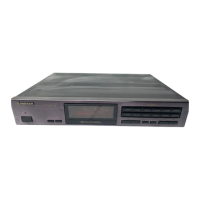
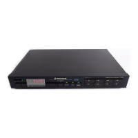
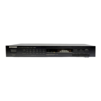
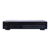
Diagram and list of external parts for the unit.

PARTS LIST

List of exterior parts and their part numbers.

BLOCK DIAGRAM AND SCHEMATIC DIAGRAM

BLOCK DIAGRAM and OVERALL CONNECTION DIAGRAM

Overall connection diagram and block diagram of the unit.

MAIN, DISPLAY AND STANDBY ASSYS

Schematic diagrams for main, display, and standby assemblies.

PCB CONNECTION DIAGRAM

PCB Diagram Notes and Symbols

Notes on reading PCB diagrams and symbol explanations.

Display and Standby Assemblies

PCB connection diagrams for display and standby assemblies.

PCB PARTS LIST

GENERAL INFORMATION

IC

Pin function details for the System Control IC (PDG231A).

PANEL FACILITIES AND SPECIFICATIONS

PANEL FACILITIES

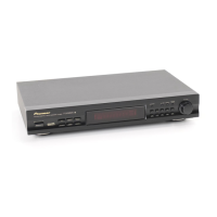
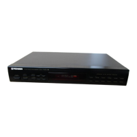
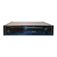
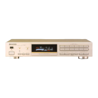
Description and operation of front panel controls and indicators.

SPECIFICATIONS

Technical specifications for FM, AM, Audio sections, and miscellaneous details.

Related product manuals