EasyManua.ls Logo

Pioneer F-91 Service Manual

Pioneer F-91
28 pages
To Next Page IconTo Next Page
Page #1 background imageLoading...
Page #1 background image
PIONEER®
The future of sound and vision.
ORDER NO.
ARP1465
Service
c714anual
FM/AN DIGITAL SYNTHESIZER TUNER
91
Origina
MODEL F-91 COMES IN FIVE VERSIONS DISTINGUISHED AS FOLLOWS:
Type
Power requirement
Export destination
KU/CA
AC120V only
U.S.A and Canada
HE
AC220V,240V (switchable) *
European continent
HB
AC220V,240V (switchable) *
United Kingdom
SD/G
AC110V,120V-127V,220V,240V (switchable)
U.S.Military
HEZ
AC220V,240V (switchable) *
West Germany
* Change the primary wiring of the power transformer.
This service manual is applicable to the
KU/CA, HE, HB, SD/G
and
HEZ
types.
As
to
the
HE, HB, SD/G
and
HEZ
types,
please refer to pages P39-P40.
Ce manuel pour le service comprend les explications en francais de reglage.(P28429)
Este manual de servicio trata del mitodo ajuste escrito en espihol. (P30-P31)
CONTENTS
1.
SPECIFICATIONS
2
8.
PACKING
.32
2.
PANEL FACILITIES
3 9.
IC INFORMATION
33
3.
EXPLODED VIEW AND PARTS LIST
5
10. BLOCK DIAGRAM
35
4.
SCHEMATIC DIAGRAM
9
11. CIRCUIT DESCRIPTION
.37
5.
P.C.BOARDS CONNECTION DIAGRAM
13
12. FOR HE, HE, HEZ AND SD/G TYPES
-39
6.
ELECTRICAL PARTS LIST
22
7.
ADJUSTMENTS
26
REGLAGE
28
AJUSTE
30
PIONEERELECTRONICCORPORATION
4-1, Meguro 1-Chome, Meguro-ku, Tokyo 153, Japan
PIONEER ELECTRONICS SERVICE INC.
P.O. Box 1760, Long Beach, California 90801 U.S.A.
PIONEER ELECTRONICS OF CANADA, INC.
505 Cochrane Drive, Markham, Ontario L3R 8E3 Canada
PIONEER ELECTRONIC [EUROPE] N.V.
Keetberglaan 1, 2740 Beveren, Belgium
PIONEER ELECTRONICS AUSTRALIA PTY. LTD.
178-184 Boundary Road, Braeside, Victoria 3195, Australia TEL: [03] 580-9911
IFIOAUG.1987 Printed in
apiP
n

Other manuals for Pioneer F-91

Question and Answer IconNeed help?

Do you have a question about the Pioneer F-91 and is the answer not in the manual?

Pioneer F-91 Specifications

General IconGeneral
Tuning BandsFM, MW
OutputFixed, Variable
Power SupplyAC 220-240V, 50/60Hz
FM Tuning Range87.5 MHz - 108.0 MHz
MW Tuning Range531 - 1602 kHz
Frequency Response (FM)20 Hz - 15 kHz
Dimensions420 x mm
TypeTuner
Output Voltage400 mV
Tuning TypePLL Quartz Synthesizer

Summary

1. SPECIFICATIONS

FM Tuner Section Specifications

Detailed technical specifications for FM reception, including sensitivity, selectivity, and S/N ratios.

AM Tuner Section Specifications

Technical specifications for AM reception, covering frequency range, sensitivity, selectivity, and S/N ratios.

2. PANEL FACILITIES

Front Panel Main Controls

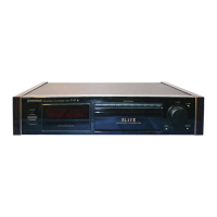
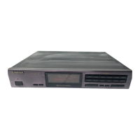
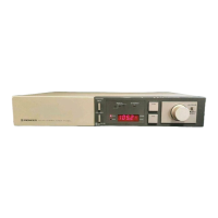
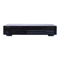
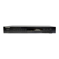
Describes POWER, PROGRAM MEMORY, TUNING UP/DOWN, and TUNING MODE controls.

Front Panel Function Switches

Explains MUTING, MPX MODE, REC LEVEL CHECK, BAND, and MEMORY switches.

Station Selection and Operation Display

Covers STATION CALL switches, [1-12/13-24] selector, and Operation Display indicators.

3. EXPLODED VIEW AND PARTS LIST

Exploded View Diagram

Visual representation of the unit's components and their assembly order.

Detailed Electrical Parts List

Comprehensive list of all electrical components, including part numbers and descriptions.

4. SCHEMATIC DIAGRAM

P.C. Boards Connection Diagram

Diagram illustrating connections between various PC boards and external components.

Overall Schematic Diagrams

Detailed electronic schematics for the tuner's circuitry across multiple pages.

6. ELECTRICAL PARTS LIST

Component Breakdown by Section

Categorized list of parts for TUNER, FL, REMOCON, and other assemblies.

COILS, FILTERS AND TRANSFORMERS

Specific listing of coils, filters, and transformers used in the unit.

Miscellaneous Components List

List of miscellaneous parts including switches, resistors, and antenna components.

7. ADJUSTMENTS

AM Section Adjustment Procedure

Step-by-step guide for adjusting the AM tuner section using specific test equipment.

FM Section Adjustment Procedure

Step-by-step guide for adjusting the FM tuner section using specific test equipment.

8. PACKING

Included Packing Components

List of parts and accessories included in the product's packaging.

9. IC INFORMATION

CX-7925B IC Pin Functions and Block Diagram

Detailed pin assignments and functional block diagram for the CX-7925B PLL IC.

PD5056 (IC502) IC Pin Functions

Detailed pin assignments and functions for the PD5056 (IC502) IC.

10. BLOCK DIAGRAM

Overall System Block Diagram

A high-level block diagram illustrating the main functional units and signal flow of the tuner.

11. CIRCUIT DESCRIPTION

New IF System Principle

Explanation of the advanced IF system design and its signal tracing characteristics.

Active Real-time Tracing System Block Diagram

Block diagram detailing the active real-time tracing system for signal processing.

12. FOR HE, HB, HEZ AND SD/G TYPES

Contrast of Miscellaneous Parts for Different Models

Comparison of miscellaneous parts across different F-91 model types.

Tuner Assembly Part Number Differences

Details on variations in tuner assembly part numbers for different F-91 models.

Related product manuals