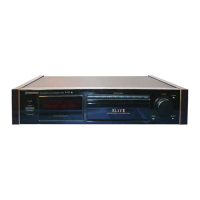
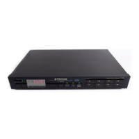
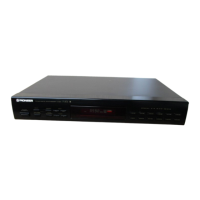
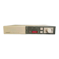
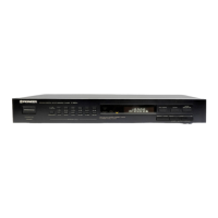
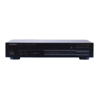
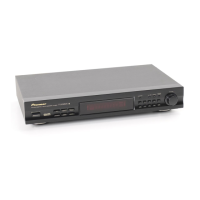
The Pioneer F-9 is an FM/AM Digital Synthesized Tuner, designed to provide high-quality radio reception with advanced digital control and display features. This service manual details its specifications, front panel facilities, block diagram, circuit descriptions, parts location, connection diagrams, and adjustment procedures.
Function Description:
The F-9 tuner operates on a PLL (Phase-Locked Loop) digital synthesis system, referenced to a crystal oscillator for precise frequency tuning. It supports both FM and AM bands with selectable channel steps and bandwidths.
FM Tuner Section:
- Front End: Utilizes two newly developed D-MOS FETs in a push-pull configuration for improved high-input characteristics, enhancing intermodulation interference elimination and sensitivity. The mixer also features a new circuit with excellent RF mutual modulation characteristics and a double-balanced mixer with an FET constant-current buffer. The tuning circuit employs four twin-type varicap diodes, contributing to superior high-input characteristics and interference elimination comparable to variable capacitor tuners.
- IF Amplifier: The FM IF circuit offers selectable WIDE and NARROW band ranges. The WIDE mode prioritizes sound quality, while the NARROW mode enhances station selectivity. It incorporates two ceramic filters with superior group delay frequency characteristics for WIDE mode and two narrow-band ceramic filters for NARROW mode. Darlington differential limiter ICs are used between stages, with the final stage using an IF system IC (PA3007) that includes a built-in noise muting (anti-hum) circuit.
- Detection Circuit: Employs a digital detection method. The 10.7MHz IF signal is converted to 1.26MHz by the PA5001 IC and then detected by the PA5002 digital detector IC. The FM signal is demodulated after conversion to a DC level, using a differential circuit to generate trigger pulses for an astable multivibrator functioning as a PPM (pulse phase modulation) signal. This method improves S/N ratio and detection efficiency.
- Multiplex Decoder: Consists of the PA4006-A IC, integrating a PLL system switching signal generator, chopper type MPX decoder, pilot signal automatic canceller, stereo auto selector, VCO killer circuit, muting amplifier, muting control circuit, and stereo reception indicator circuit. The chopper type switching circuit ensures noise and distortion-free signal establishment.
AM Tuner Section:
- Uses three varicap diodes and an AM tuner IC (HA1138).
- Features selectable WIDE and NARROW IF bands for sound quality and selectivity, respectively. The NARROW band operation includes an additional ceramic filter and a high-pass filter to eliminate low-frequency beat and improve audio frequency band balance.
- An AGC circuit within the IC suppresses performance degradation in strong magnetic fields. The bar-antenna includes a cancellation coil controlled by a high-powered AGC circuit.
- Muting control and SIGNAL indicator control are managed by signals from Q24-Q26.
Synthesizer Circuit:
- A quartz PLL synthesizer system comprising a voltage-controlled oscillator (VCO), programmable counter, phase comparator, reference oscillator, and loop filter. The F-9 uses a one-chip C-MOS IC (TC9137P) with a high-speed prescaler (TD6104P) in a dual programmable counter configuration, providing split ratio prescaling via the pulse swallow count method. This sets the reference frequency at 25kHz (outside the audible range), reducing noise and improving S/N.
- Reference Signal: A 7.2MHz crystal oscillator signal is divided to 25kHz for FM and 10kHz for AM, then input to the phase comparator.
- Programmable Counter: Controls the prescaler IC for FM reception using the swallow count method, and directly splits frequency for AM reception.
- Phase Comparator: Compares the phase of the programmable counter output with the reference signal, adjusting output levels to correct phase lag or advance. The output is integrated through a low-pass filter and applied to the VCO varicap diode.
Synthesizer System Control:
- The TC9137P IC manages operation modes (FM/AM band designation, local power supply requirements) and tuning modes (manual/auto).
- Manual Tuning: Allows frequency increment/decrement in steps (100kHz for FM, 10kHz for AM) or rapid scanning when UP/DOWN keys are held.
- Auto Search Tuning: In AUTO mode, the unit automatically scans the frequency band, stopping at stations exceeding a prescribed signal strength.
- Memory: Stores up to 6 FM and 6 AM frequencies. A special memory retains the last tuned station even when power is off.
- Indicators: Includes a 7-segment LED numeric display for frequency (5 digits for FM, 4 for AM), a 5-point LED signal strength indicator, FM/AM band indicators (flashing during memory write status), and STATION indicators for memory addresses.
Frequency Display Circuit:
- The TC9137P synthesizer IC uses the TD6301P static driver IC to convert 5-digit LED numeric display data to a 4-digit display.
- Data transmission involves two timing signal lines and one data signal line, transmitting a 16-bit binary code (11 bits for frequency, 5 for band data).
- The 5th digit for FM reception displays "0" or "5" (10kHz increments) controlled by TC9137P pin 23, switching via Q35 and Q34.
Important Technical Specifications:
FM Tuner Section:
- Usable Sensitivity: Mono; 10.8 dBf (0.95 µV)
- 50 dB Quieting Sensitivity: Mono; 15 dBf (1.55 µV), Stereo; 37 dBf (19.5 µV)
- Signal-to-Noise Ratio (at 85 dBf): Mono; 90 dB, Stereo; 85 dB
- Distortion (at 85 dBf):
- WIDE: 100 Hz: 0.03%, 1 kHz: 0.03%, 10 kHz: 0.03% (Mono)
- NARROW: 1 kHz: 0.05%, 10 kHz: 0.1% (Stereo)
- Capture Ratio: 1.0 dB (WIDE), 2.5 dB (NARROW)
- Alternate Channel Selectivity: 400 kHz: 40 dB (WIDE), 85 dB (NARROW); 300 kHz: 60 dB (NARROW)
- Stereo Separation: 1 kHz: 55 dB, 50 Hz to 10 kHz: 48 dB
- Frequency Response: 20 Hz to 15 kHz ±0 dB
- Spurious Response Ratio: 80 dB
- Image Response Ratio: 70 dB
- IF Response Ratio: 100 dB
- AM Suppression Ratio: 65 dB
- Subcarrier Product Ratio: 70 dB
- SCA Rejection Ratio: 65 dB
- Muting Threshold: 25.2 dBf (5 µV)
- Antenna Input: 300 ohms balanced, 75 ohms unbalanced
AM Tuner Section:
- Sensitivity: IHF, ferrite antenna: 300 µV/m, IHF, external antenna: 15 µV
Audio Section:
- Output (100% MOD): FM: FIXED 650 mV/1.1 kΩ, AM: FIXED 200 mV/1.1 kΩ
General:
- Power Requirements: 120 V, 60 Hz
- Power Consumption: 17 W (UL/CSA)
- Dimensions: 420 (W) x 60 (H) x 380 (D) mm (16-1/2 (W) x 2-3/8 (H) x 15 (D) in)
- Weight (without package): 4.5 kg (9 lb 15 oz)
Usage Features:
- Door: Conceals internal switches, to be kept closed during normal operation.
- Recording Level Check Switch (REC LEVEL CHECK): Provides a 330 Hz, FM 50% modulation reference signal for recording.
- IF Bandwidth Selector Switch (IF BAND): Selects WIDE for strong signals and reduced distortion, or NARROW for improved selectivity in areas with interference.
- Mode Switch (MODE): AUTO for automatic stereo/mono switching, MONO for forced mono reception in noisy or weak signal areas.
- Tuning Switches (TUNING): UP/DOWN buttons for frequency adjustment. In AUTO mode, tuning continues until a station is found. In MANUAL mode, tuning is step-by-step and stops when the button is released.
- Memory Switch (MEMORY): Stores stations into STATION CALL switches [1] through [6].
- Tuning Mode Switch (TUNING MODE): Selects AUTO or MANUAL tuning.
- Power Switch (POWER): Turns the unit on/off. Even in STAND-BY, some circuitry remains active if connected to power outlet.
- IF WIDE Indicator: Lights when IF BAND is set to WIDE.
- Signal Indicator: Five LEDs indicate signal strength.
- Stereo Indicator: Lights during FM stereo reception (not in MONO mode).
- Multipath Indicator: Lights when multipath effect is detected; used for antenna adjustment.
- FM/AM Indicators: Indicate selected band and flash during memory write status.
- Frequency Display: Shows tuned frequency in MHz (FM) or kHz (AM).
- Function Switches (FM, AM): Selects FM or AM band.
- Station Call Switches (STATION CALL): Recalls memorized stations.
- Station Indicators: Lights corresponding to the recalled station (top row for FM, bottom for AM).
Maintenance Features:
- Memory Hold: The TC9137P IC maintains memory contents even when the power switch is off (STANDBY) or the AC line cord is unplugged (for approximately 3 days, using a backup capacitor C184).
- Inhibit Function: TC9137P has a self-contained inhibit function, setting all functions to a static condition (oscillations stopped, inputs locked, indicator drives off, outputs to L level) to minimize power consumption (approx. 10µA) during standby.
- Q44 Function: Prevents IC current drain when pins 34 and 33 go into an inhibit status (H level), by turning off Q44.
- Parts List: Detailed electrical parts list for components like transformers, capacitors, resistors, and semiconductors, including part numbers, symbols, and descriptions. Special markings indicate critical safety parts and fast-moving items for stock control.
- Exploded Views: Diagrams for exterior and interior components, aiding in disassembly and reassembly.
- Adjustment Procedures: Comprehensive instructions for FM Tuner, FM Multiplex Decoder, AM Tuner, and REC Level Check Signal Generator adjustments, including frequency, level, display, adjustment points, and methods. These procedures are crucial for proper device calibration and repair.
- Service Manual Variations: This manual is applicable to the KU type. Additional service manuals (ART-613, ART-614, ART-612) are referenced for HE, HB, S, S/G, and KC types, indicating regional variations in voltage and channel steps.