EasyManua.ls Logo

Pioneer F-93 User Manual

Pioneer F-93
16 pages
To Next Page IconTo Next Page
Page #1 background imageLoading...
Page #1 background image
FM/AM
DIGITAL
SYNTHESIZER
TUNER
mes,
Operating
Instructions
2
PIONEER
meen
orn
eorenen
moan
F-93
Thank
you
for
buying
this
Pioneer
product.
Please
read
through
these
operating
instructions
so
you
will
know
how
to
operate
your
model
properly.
After
you
have
finished
reading
the
instructions,
put
them
away
in
a
safe
place
for
future
reference.
*
In
some
countries
or
regions,
the
shape
of
the
power
plug
and
power
outlet
may
sometimes
différ
from
that
shown
in
the
explanatory
drawings.
However,
the
method
of
connecting
and
operating
the
unit
is
the
same.
WARNING:
to
prevENT
FIRE
OR
SHOCK
HAZARD,
DO
NOT
EXPOSE
THIS
APPLIANCE
TO
RAIN
OR
MOISTURE.
IMPORTANT
NOTICE
{For
U.S.
and
Canadian
models]
The
serial
number
for
this
equipment
is
located
on
the
rear
panel.
Please
write
this
serial
number
onyour
enclosed
warranty
card
and
keep
it
in
a
secure
area,
This
is
for
your
security.
[For
Canadian
model]
CAUTION:
to
prevent
ELECTRIC
SHOCK
DO
NOT
USE
THIS
(POLARIZED)
PLUG
WITH
AN
EXTENSION
CORD,
RECEPTACLE
OR
OTHER
OUTLET
UNLESS
THE
BLADES
CAN
BE
FULLY
INSERTED
TO
PREVENT
BLADE
EXPOSURE.
ATTENTION:
pour
prevenir
Des
CHOCS
ELECTRIQUES
EN
PAS
UTILISER
CETTE
FICHE
POLARISEE
AVEC
UN
PROLONGA-
TEUR
UNE
PRISE
DE
COURANT
OU
UNE
AUTRE
SORTIE
DE
COURANT,
SAUF
SI
LES
LAMES
PEUVENT
ETRE
INSEREES
A
FOND
SANS
EN
LAISSER
AUCUNE
PARTIE
A
DEGOUVERT.
Note
to
CATV
system
installer
This
reminder
is
provided
to
call
the
CATV
system
installer’s
attention
to
Article
820-22
of
the
NEC
that
provides
guidelines
for
proper
grounding
and,
in
particular,
specifies
that
the
cable
ground
shall
be
connected
to
the
grounding
system
of
the
building,
as
close
to
the
point
of
cable
entry
as
practical.
LINE
VOLTAGE
SELECTOR
SWITCH
Only
multi-voltage
models
are
provided
with
this
switch.
U.S.,
Canadian,
European,
U.K.,
and
Australian
models
are
not
provided
with
this
switch.
Mains
voltages
in
Saudi
Arabia
are
127
V
and
220
V
only.
Never
use
this
model
with
110
V
setting
in
Saudi
Arabia.
You
will
find
the
line
voltage
selector
switch
on
the
rear
panel.
Before
your
model
is
shipped
from
the
iactory,
th
set
to
the
power
requirements
of
the
destination;
r
you
should
check
that
itis
set
properly
before
plugging
the
pow:
ard
inte
tHe
AC
puter.
Hf
the
voltage
is
not
properly
set,
or
if
you
move
to
an
area
where
the
voltage
requirements
differ,
adjust
the
selector
switch
as
follows.
Before
adjusting,
disconnect
the
power
cord.
1.
Provide
yourself
with
a
medium:
sizi
wer
2.
Using
the
screwdriver
turn
until
the
arrow
points
to
the
voltage
level
of
your
area.
“VOLTAGE SELECTOR
=
HO
127
Medium-size
screwdriver
©)
PIONEER’
The
Art
of
Entertainment

Other manuals for Pioneer F-93

Question and Answer IconNeed help?

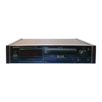
Do you have a question about the Pioneer F-93 and is the answer not in the manual?

Pioneer F-93 Specifications

FM Tuner Specifications IconFM Tuner Specifications
FM frequency range87.5 MHz to 108 MHz
FM usable sensitivity11.2 dBf
FM signal-to-noise ratio96 dB
AM Tuner Specifications IconAM Tuner Specifications
AM frequency range530 kHz to 1, 700 kHz
AM sensitivity150 AV/m
AM signal-to-noise ratio50 dB
Audio Output IconAudio Output
Output level1, 000 mV
Output impedance0.5 kΩ
Distortion at 80 dBf0.03 % (1 kHz)
Power IconPower
U.K. model power requirementsAC 240 V, 50/60 Hz
U.S., Canadian models power requirementsAC 120 V, 60 Hz
Multi-voltage model power requirementsAC 110 V/120 - 127 V/220 V/240 V, 50/60 Hz
Physical Characteristics IconPhysical Characteristics
Dimensions420 x 106 x 327 mm
Dimensions (inches)16-1/2 x 4-3/16 x 12-7/8 in
Weight6.5 kg

Summary

Important Notices and Warnings

Warning: Fire or Shock Hazard

Do not expose the appliance to rain or moisture to prevent fire or shock.

Caution: Electric Shock Prevention

Do not use a polarized plug with an extension cord or outlet unless blades are fully inserted.

Note to CATV System Installer

Guidelines for proper grounding of the cable ground connection.

Line Voltage Selector Switch

Important Safety Information

Risk of Electric Shock: Do Not Open

Refer servicing to qualified personnel; no user-serviceable parts inside.

Caution: Prevent Electric Shock Risk

Do not remove the cover to prevent electric shock.

General Safety Instructions

Water and Moisture Precautions

Avoid using the appliance near water or in wet locations.

Location and Ventilation Guidelines

Install in a stable location with proper ventilation, away from heat sources.

Power Cord and Cleaning Safety

Protect power cords and clean the unit with a dry cloth.

Service and Damage Handling

Service required for damaged cords, spilled liquids, or abnormal operation.

Outdoor Antenna Grounding

Features Overview

High Receivability

Improved front end and IF circuitry for better interference rejection and selectivity.

High Specification

Achieves high S/N ratio, low distortion, and superior separation with DDD Type IV.

High Sound Quality

Features FDNR audio stage L.P.F. and anti-vibration design for enhanced audio.

High Controllability

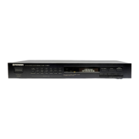
Offers direct access, fine tuning, auto operation, 40-station presets, and dual output jacks.

Channel Step/FM De-emphasis Switch

Connections

Connection Example

Illustrates how to connect outdoor FM antennas, AM loop antenna, and audio output.

Connecting the AM Loop Antenna

Step-by-step guide for connecting the AM loop antenna.

Connection Details

Pin Plug Connecting Cord

Instructions for connecting the audio output via pin plugs.

Power Cord Connection

Procedure for connecting the power cord, noting polarity.

Attach Antenna Adaptor

Guide for attaching the antenna adaptor for 75 Ohm coaxial cable and 300 Ohm feeder.

Antenna Connections

AM Antenna Setup

Guidance on connecting and positioning the AM loop and external antennas.

FM Antenna Attachment

Instructions for connecting the T-type FM antenna and external antennas.

Antenna Grounding

Importance and method of grounding for lightning protection and noise reduction.

Rear Panel Facilities

Antenna Jacks

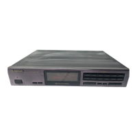
Description of FM and AM antenna connection terminals.

Output Jacks

Explanation of FIXED and VARIABLE output jacks for amplifier connection.

Power Cord Connection

Details on connecting the power cord, emphasizing polarity for sound quality.

Control Jacks

Overview of IN/OUT jacks for Pioneer remote control signals.

Front Panel Facilities

Power Standby/On Switch

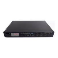
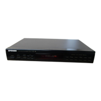
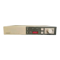
Description of the power switch and its standby indicator.

Operation Display

Reference to page 10 for detailed explanation of the operation display.

Station Call and Tuning Buttons

Use of Station Call buttons for presets and direct access tuning.

Hinged Panel Controls

Controls located behind the hinged panel: Auto Operation and MPX NR.

Front Panel Controls Explained

SSS Button

Enables simulated stereo effect for monaural sources.

Auto Level Button

Sets signal threshold levels for auto tuning stop.

S-MPX Button

Switches to SUPER NARROW IF BAND and AUTO MPX MODE for interference.

Memory and Band Selection

Functions for memorizing stations and selecting FM/AM bands.

Antenna and RF Attenuation Control

Selects antennas (A/B) and applies RF attenuation for strong signals.

IF Band and MPX Mode

Adjusts IF bandwidth and multiplex mode for optimal reception.

Fine Tuning and Direct Input

Fine-tuning for noise reduction and direct frequency input using station call buttons.

Operation Display Indicators

Frequency and Class Indicators

Displays reception band/frequency and selected preset memory class.

Signal and Level Indicators

Shows signal strength, station recall, RF ATT level, and auto level settings.

Mode and Status Indicators

Indicates Auto Operation, S-MPX, Memory, Fine Tuning, SSS, and MPX NR status.

Antenna and IF Band Indicators

Shows selected antenna (A/B) and IF Band mode (Normal/Super Narrow).

MPX Mode Indicators

Displays selected MPX mode (Auto, Mono) and Stereo reception status.

Listening to Broadcasts

Tuning into Stations

Manual and auto tuning procedures for receiving desired stations.

Signal Indicator Explanation

Interpreting signal strength and troubleshooting weak reception.

Handling Interference and Noise

Using IF BAND, S-MPX, FINE TUNING, RF ATT, and MPX MODE for noise reduction.

Simulated Stereo for Monaural

Using the SSS button to enjoy simulated stereo with monaural broadcasts.

Direct Access Tuning

Fine Tuning

Presetting Stations

Station Preset Procedures

Step-by-step guide to memorizing stations into 4 classes and 40 presets.

Preset Station Tuning

How to recall and listen to memorized preset stations.

Last Station Memory

The unit remembers the last tuned station after power off.

Troubleshooting Guide

No Power or Sound Issues

Diagnosing and resolving problems related to power and sound output.

Station Selection and Noise

Troubleshooting station tuning failures and reception noise.

Sound Distortion and Stereo Issues

Resolving sound distortion and problems with FM stereo reception.

Specifications

FM Tuner Section

Technical specifications for the FM tuner, including sensitivity and selectivity.

AM Tuner Section

Technical specifications for the AM tuner, including frequency range and sensitivity.

Audio and Miscellaneous Specs

Specifications for audio output, power requirements, dimensions, and furnished parts.

Maintenance of External Surfaces

Related product manuals