EasyManua.ls Logo

Pioneer GM-2137ZF/X1R/UC User Manual

Pioneer GM-2137ZF/X1R/UC
22 pages
To Next Page IconTo Next Page
Page #1 background imageLoading...
Page #1 background image
PIONEER CORPORATION 4-1, Meguro 1-Chome, Meguro-ku, Tokyo 153-8654, Japan
PIONEER ELECTRONICS (USA) INC. P.O.Box 1760, Long Beach, CA 90801-1760 U.S.A.
PIONEER EUROPE NV Haven 1087 Keetberglaan 1, 9120 Melsele, Belgium
PIONEER ELECTRONICS ASIACENTRE PTE.LTD. 253 Alexandra Road, #04-01, Singapore 159936
C PIONEER CORPORATION 2004
K-ZZB. JAN. 2004 Printed in Japan
ORDER NO.
CRT3216
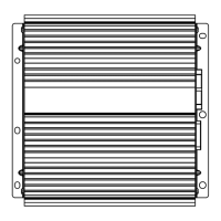
6 ch POWER AMPLIFIER
GM-2137
ZFX1R/UC
Service
Manual
FORD
VEHICLE DESTINATION PRODUCED AFTER FORD PART No. ID No. PIONEER MODEL No.
Lincoln Navigator U.S.A., CANADA October 2003 4L7T-18C808-AD GM-2137ZF/X1R/UC
Lincoln Aviator
Lincoln Town Car
Ford Ranger (Tremor ā€)
Ford Sport Track (Adrenalin)
GM-2137ZF/X1R/UC
For details, refer to "Important symbols for good services".
Question and Answer IconNeed help?

Do you have a question about the Pioneer GM-2137ZF/X1R/UC and is the answer not in the manual?

Pioneer GM-2137ZF/X1R/UC Specifications

General IconGeneral
BrandPioneer
ModelGM-2137ZF/X1R/UC
CategoryAmplifier
LanguageEnglish

Summary

Important Symbols for Good Services

Product Safety Guidelines

Ensures compliance with regulations and safety during servicing.

Adjustment Procedures

Maintaining original product performance through proper adjustments.

Cleaning Procedures

Guidelines for cleaning optical pickups and other sensitive parts.

Shipping Mode and Screws

Instructions for setting shipping mode and installing screws.

Lubricants, Glues, and Parts

Proper use of lubricants, glues, and recommended replacement parts.

Safety Information

Specifications

Exploded Views and Parts List

Packing Components

Exploded view and parts list for packing items.

Exterior View

Exterior Parts List

Schematic Diagram

Schematic Diagram Guide Page

Guide page for understanding the main schematic diagram.

PCB Connection Diagram

Amp Unit PCB Connections

PCB connection diagram for the amplifier unit.

Electrical Parts List

Adjustment

General Information

Diagnosis and Disassembly

Procedures for diagnosing and disassembling the unit.

Connector Function Description

IC Details: TDA1562ST

System Block Diagram

Operations

Related product manuals