Section
ID ( Connecting
the
units
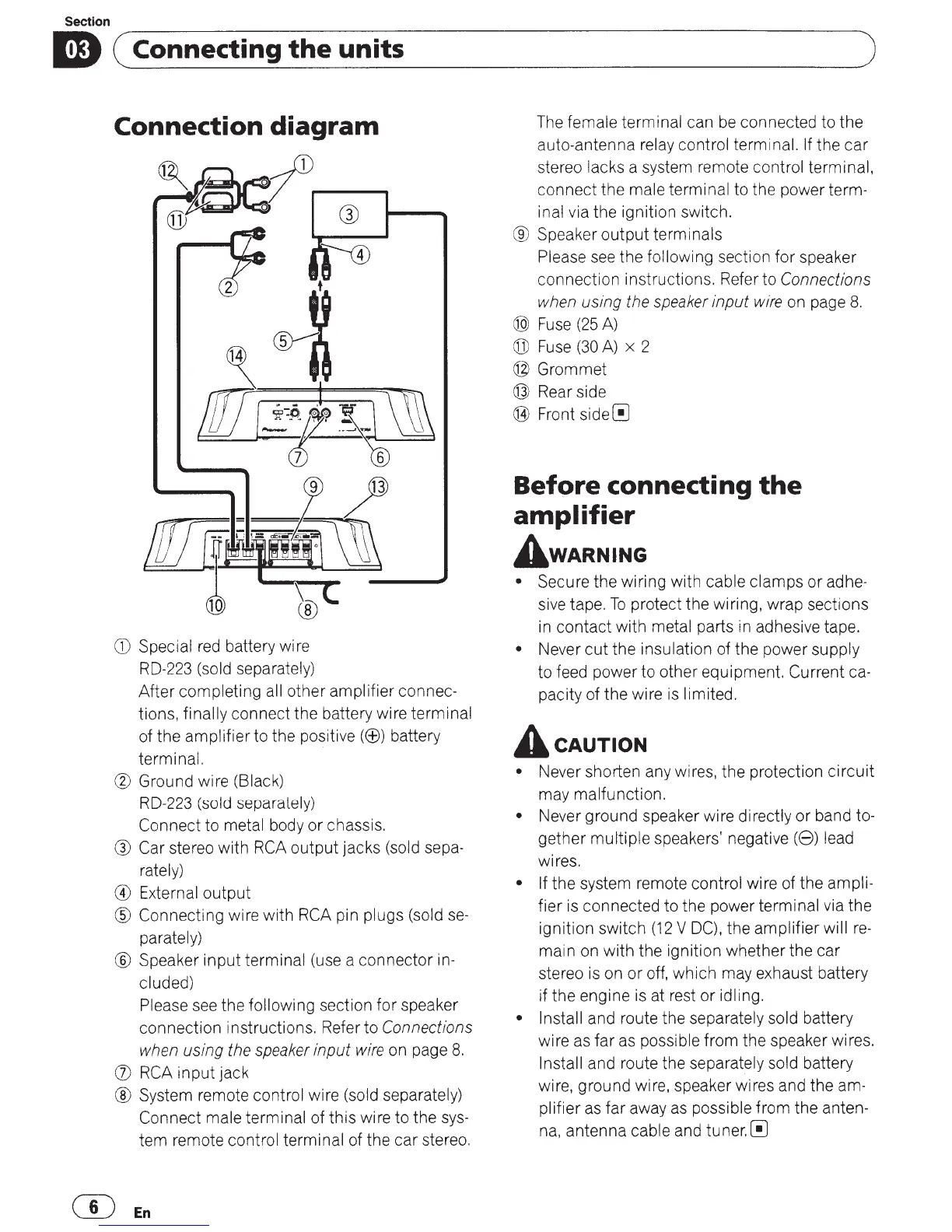
Connection
diagram
CD
Special
red
battery wire
RD-223
(sold separately)
After completing all other amplifier connec-
tions, finally connect the battery wire terminal
of the amplifier to the positive((±)) battery
terminal.
® Ground wire (Black)
RD-223 (sold separately)
Connect to metal body or chassis.
® Car stereo with
RCA
output jacks (sold sepa-
rately)
® External output
® Connecting wire with RCA pin plugs (sold
se-
parately)
® Speaker input terminal (use a connector in-
cluded)
Please
see
the following section for speaker
connection instructions. Refer to
Connections
when
using
the
speaker
input
wire
on page
8.
OJ
RCA
input jack
® System remote control wire (sold separately)
Connect male terminal of this wire to the
sys-
tem remote control terminal of the car stereo.
mEn
)
The
female terminal can
be
connected to the
auto-antenna relay control terminal.
If
the car
stereo lacks a system remote control terminal,
connect the male terminal to the power term-
inal via the ignition switch.
® Speaker
output
terminals
Please
see
the following section for speaker
connection instructions. Refer to
Connections
when
using the
speaker
input
wire
on page
8.
@
Fuse
(25
A)
(j])
Fuse
(30
A)
x 2
@Grommet
@ Rear side
@ Front
side[!]
Before connecting
the
amplifier
A wARNING
• Secure the wiring with cable clamps
or
adhe-
sive tape.
To
protect the wiring, wrap sections
in
contact with metal parts
in
adhesive tape.
• Never
cut
the insulation of the power supply
to feed power to other equipment. Current ca-
pacity of the wire
is
limited.
A
cAUTION
• Never shorten any wires, the protection
circuit
may malfunction.
• Never ground speaker wire directly
or
band to-
gether multiple speakers' negative
(8)
lead
wires.
• If the system remote control wire of the ampli-
fier
is
connected to the power terminal via the
ignition switch
(12
V
DC),
the amplifier will
re-
main on with the ignition whether the car
stereo
is
on
or
off, which may exhaust battery
if the engine
is
at rest
or
idling.
• Install and route the separately sold battery
wire as far
as
possible from the speaker wires.
Install and route the separately sold battery
wire, ground wire, speaker wires and the am-
plifier
as
far away
as
possible from the anten-
na,
antenna cable and
tuner.[!]
 Loading...