This document is an owner's manual for Pioneer GM-A5602 and GM-A3602 bridgeable two-channel power amplifiers. It provides comprehensive information on the device's functions, usage, and maintenance, ensuring users can operate the product safely and effectively.
Function Description
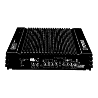
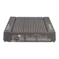
The Pioneer GM-A5602 and GM-A3602 are bridgeable two-channel power amplifiers designed to enhance the audio experience in vehicles. These amplifiers can operate in either two-channel (stereo) or one-channel (mono/bridged) output modes, offering flexibility for various speaker configurations, including subwoofers and full-range speakers. The "bridgeable" feature allows users to combine the power of both channels into a single, more powerful output, ideal for driving subwoofers.
Key functions include:
- LPF (Low-Pass Filter) Switch: This switch allows users to select between "ON" and "OFF" modes. When a subwoofer is connected, setting the LPF to "ON" eliminates high-range frequencies, outputting only low-range frequencies suitable for subwoofers. When a full-range speaker is connected, setting it to "OFF" allows the amplifier to output the entire frequency range.
- FREQ (Cut-Off Frequency) Control: This control is active when the LPF switch is set to "ON." It enables users to select a cut-off frequency ranging from 40 Hz to 500 Hz, allowing for precise tuning of the low-pass filter to match the connected subwoofer and achieve optimal bass response.
- BASS BOOST (Bass Boost Level Control) Switch: This feature allows users to select a bass boost level of 0 dB, 6 dB, or 12 dB. This function enhances low-frequency output, providing a more impactful bass experience.
- GAIN Control: The gain control adjusts the input sensitivity of the amplifier. Users can set it to "NORMAL" for RCA-equipped car stereos with a standard output of 500 mV or higher. For RCA-equipped Pioneer car stereos with a maximum output of 4 V or more, the gain should be adjusted to match the car stereo's output. For car stereos with an RCA output of 4 V, the "HIGH" position is recommended. If excessive noise is heard when using the speaker input terminals, increasing the gain control level can help.
- Protection Function: The amplifier incorporates a protection function to prevent malfunction of the unit and/or speakers due to excessive output, improper use, or incorrect connections. In situations like short-circuited speaker output terminals, a DC voltage applied to the speaker output, or high internal temperatures, the power indicator will turn off, and the amplifier will shut down to prevent damage. If the temperature gets too high, the amplifier will reduce power output before shutting down.
Usage Features
The manual emphasizes proper installation and connection procedures to ensure safe and optimal performance.
- Speaker Connection: The amplifier supports both two-channel (stereo) and one-channel (mono) output modes. Detailed instructions are provided for connecting speaker leads according to the chosen mode. For bridged mode, specific impedance requirements (4Ω load, achieved with two 8Ω speakers in parallel or a single 4Ω speaker) are highlighted to prevent damage.
- Power Terminal Connection: A special red battery and ground wire (RD-223, sold separately) are recommended. The battery wire should be connected directly to the car battery's positive terminal, and the ground wire to the car body. The manual provides step-by-step instructions for routing the battery wire from the engine compartment to the vehicle interior, including precautions for drilling cable pass-holes.
- Speaker Input Wire Connection: For car stereos without RCA output jacks, the supplied speaker input wire can be used to connect the car stereo's speaker output wires to the amplifier. It's crucial not to connect both RCA input and speaker input at the same time. The amplifier can automatically turn on and off with the head unit when using speaker input wires, though this function may not work with all head units.
- System Remote Control Wire: This wire connects the amplifier to the car stereo's system remote control terminal. If the car stereo lacks this terminal, the male terminal of the remote control wire can be connected to the power terminal via the ignition switch. However, this may cause the amplifier to remain on with the ignition, potentially draining the battery.
- Gain Setting: Proper gain setting is crucial to prevent distortion and ensure continuous sound output. The manual explains how to set the gain control based on the preout maximum output level of the head unit. It also illustrates the relationship between amplifier gain and head unit output power, emphasizing that improper gain settings can increase distortion without significantly increasing power.
- Installation Location: The amplifier should be installed on a flat, rigid surface, ensuring adequate space for proper ventilation. It should not be covered by floor mats or carpets, and cables should be routed away from hot places like heater outlets. The manual advises against installing the amplifier in locations where it could injure occupants or interfere with the driver.
Maintenance Features
The manual provides important guidelines for maintaining the amplifier and ensuring its longevity.
- Fuse Replacement: If the fuse of the battery wire or amplifier blows, users should check the power supply and speaker connections to determine and resolve the cause before replacing the fuse with an identical equivalent. Always use a fuse of the rating prescribed to prevent overheating, smoke, damage, and injury.
- Abnormality Check: In case of any abnormality, the amplifier's protection function will cut off the power supply. Users should switch off the system power, check the power supply and speaker connections, and contact their dealer if the cause cannot be determined.
- Wiring Security: All wiring, including power supply, ground, and speaker wires, should be secured with cable clamps or adhesive tape. Sections in contact with metal parts should be wrapped in adhesive tape to prevent damage and short circuits. It's crucial not to cut the insulation of the power supply wire to feed power to other equipment, as its current capacity is limited.
- Battery Disconnection: Always disconnect the negative terminal of the battery before installation to avoid electric shock or short circuits.
- No Disassembly or Modification: Users are warned not to disassemble or modify the unit, as this could result in fire, electric shock, or other malfunctions.
- Speaker Specifications: Ensure that connected speakers conform to the specified impedance (2Ω to 8Ω for stereo, 4Ω to 8Ω for monaural/bridged connection) to prevent fire, smoke, or damage.
- Regular Checks: Before final installation, all connections and systems should be checked. After installation, confirm that the spare tire, jack, and tools can be easily removed.
- Cleaning: While not explicitly detailed, general electronic device maintenance practices like keeping the unit free from dust and liquids are implied to prevent malfunction and electrical shock. The manual specifically warns against allowing the unit to come into contact with liquids.
By adhering to these instructions, users can ensure the safe, efficient, and long-lasting operation of their Pioneer GM-A5602 or GM-A3602 power amplifier.